A method for automatically generating quadrilateral finite element meshes for pitting damaged cylindrical shells

A cylindrical shell and finite element technology, applied in the field of parametric construction of cylindrical shell models, to achieve the effect of improving the solution accuracy and efficiency

Active Publication Date: 2017-06-23
HUAWEI TEHCHNOLOGIES CO LTD
View PDF4 Cites 2 Cited by
  • Summary
  • Abstract
  • Description
  • Claims
  • Application Information

AI Technical Summary

Problems solved by technology

[0004] The main purpose of the present invention is to provide a method for automatically generating quadrilateral finite element meshes of cylindrical shells with pitting damage, improve the meshing quality of finite element models of cylindrical shells with local damage, thereby solve the problem of describing physical models of different scales, and improve the simulation performance. Computational solution accuracy and efficiency

Method used


Image

  • A method for automatically generating quadrilateral finite element meshes for pitting damaged cylindrical shells
  • A method for automatically generating quadrilateral finite element meshes for pitting damaged cylindrical shells
  • A method for automatically generating quadrilateral finite element meshes for pitting damaged cylindrical shells

Examples


Embodiment

[0064] Taking a pitting damaged cylindrical shell of an experimental model as an example, the finite element software adopts ANSYS to illustrate the present invention, and an automatic generation method of finite element model grids including physical models of different scales is given.

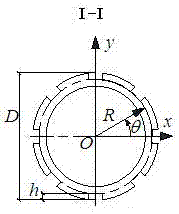
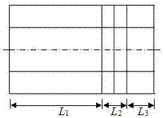
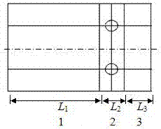
[0065] Step 1: Set the key geometric dimension as the main parameter, see figure 1 and figure 2 .

[0066] Parametrically set the key dimensions of the cylindrical shell in the finite element software, and the key dimension parameters include: the mid-surface radius of the cylindrical shell R =21mm, shell thickness t =8mm, cylindrical shell length L =200mm, outer diameter of round tube D =2 R + t =50mm; depth of pitting damage h =4mm, pitting damage diameter d =6mm, length of pitting affected area l = d / 2=3mm, the number of pits in the circumferential direction M =6, the number of pit layers in the longitudinal axis N =5; the length of the perfect zone at the end L 1 =44mm. ...


PUM


Abstract

The invention discloses a method for automatically generating a quadrilateral finite element grid of a pitting damaged cylindrical shell. In the finite element software, the key geometric dimensions of the pitting damaged cylindrical shell model are parameterized, and the cylindrical shell is constructed through segmental expression. The three standard basic segments of end perfect area, pitting area and pitting spacer, use the method of copy, translation and segmentation to construct the whole point including multi-layer pitting area, pitting spacer and end perfecting area For the geometric model of the corroded cylindrical shell, the geometric model is grouped according to the position of the pit and the size characteristics of each partition, and the number of grid divisions for the boundary of each grouped object area is set, and the overall model of the cylindrical shell is divided by mapping MAPPED and AMAP, and finally a quadrilateral is generated The overall finite element model of the grid unit solves the problem of fine pitting damage description in the macro-scale structure, and improves the solution accuracy and efficiency of the simulation calculation.

Description

technical field [0001] The present invention relates to a finite element modeling method for pitting damaged cylindrical shells, more specifically, the present invention relates to a quadrilateral grid division that can be used to more accurately analyze the stress concentration and point damage caused by local damage of cylindrical shells Corrosion damage evolution and the parametric construction method of cylindrical shell model for studying the law of pitting damage affecting structural bearing capacity. Background technique [0002] Most of the legs of the pile-based platform work in a state of being eroded by the marine environment, especially in the spray splash area, which is the area where the platform structure is most severely damaged by corrosion. Corrosion will weaken the ultimate strength of components, and the influence of local damage such as pitting and grooves on the strength of components is more complicated. Usually, for the convenience of processing, such...

Claims


Application Information

Patent Timeline
Patent Type & Authority Patents(China)
IPC IPC(8): G06F17/50
Inventor 王仁华方媛媛
Owner HUAWEI TEHCHNOLOGIES CO LTD
Why Eureka
Try Eureka