
Self balance type punching riveting gun and control method thereof

A self-balancing, punching riveting technology, which is applied in the field of self-balancing riveting guns and its control, can solve the problems of time-consuming and labor-consuming programming of punching riveting robots, insufficient occlusal amount of riveting points, and shape and position deviation of connecting parts. Achieve the effects of shortening the programming time, ensuring the quality of punching and riveting, and eliminating the deviation of shape and position

Inactive Publication Date: 2015-04-08
ANHUI JEE AUTOMATION EQUIP CO LTD
View PDF5 Cites 3 Cited by
  • Summary
  • Abstract
  • Description
  • Claims
  • Application Information

AI Technical Summary

Problems solved by technology

However, the rivet gun in the prior art is limited by its own mechanical structure, which makes the programming process of the rivet robot time-consuming and labor-intensive.
And because of the deviation of the shape and position of the connector itself, it is easy to cause quality defects such as deformation of the plate after riveting, insufficient occlusal amount of riveting points, and insufficient strength.

Method used


Image

  • Self balance type punching riveting gun and control method thereof
  • Self balance type punching riveting gun and control method thereof
  • Self balance type punching riveting gun and control method thereof

Examples


Embodiment Construction

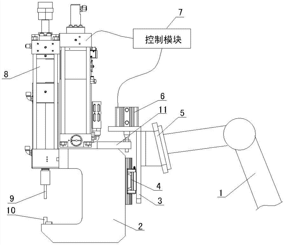
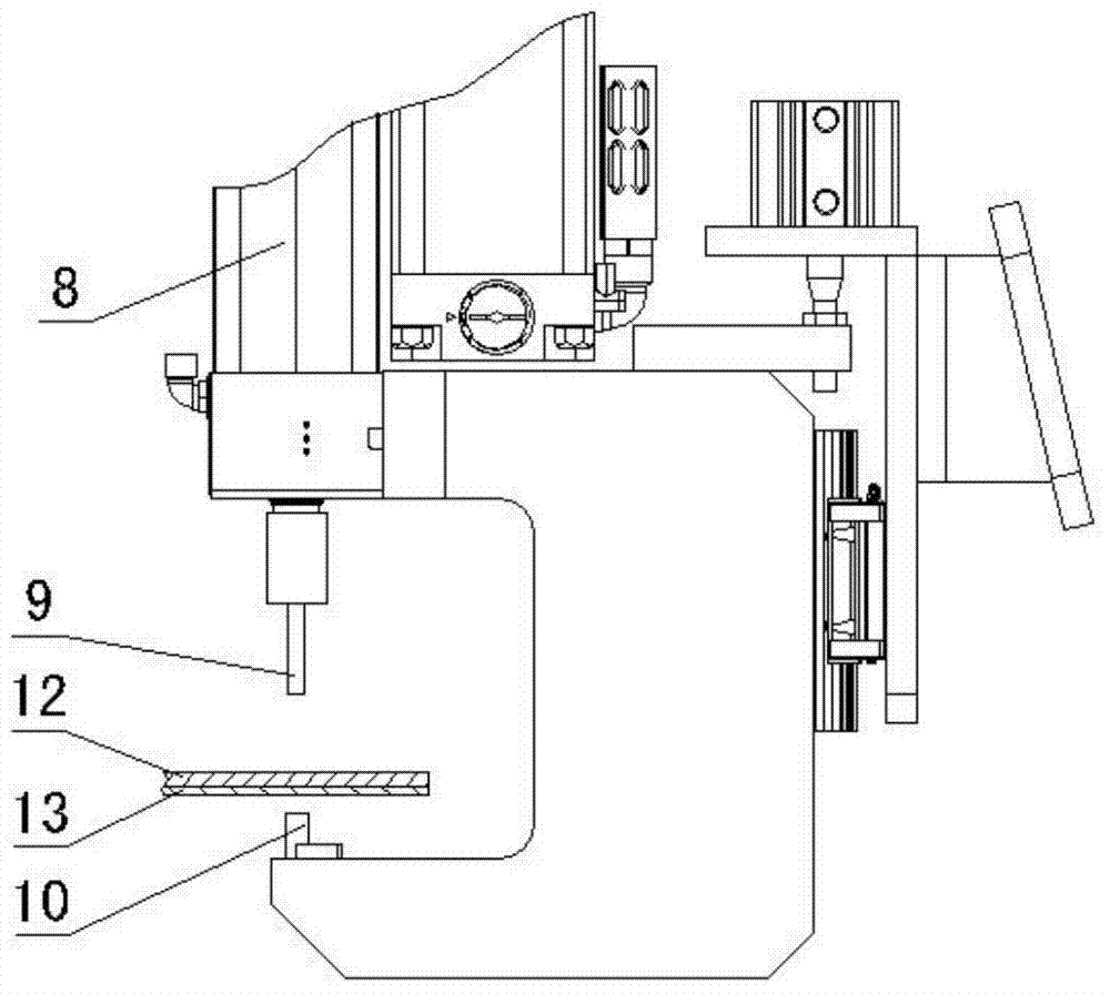
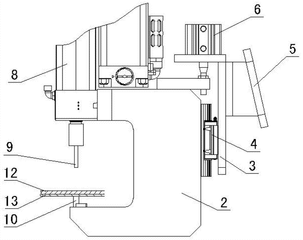
[0020] see figure 1 , the structural form of the self-balancing riveting gun in this embodiment is:

[0021] With the bracket 3 as the base, the bracket 3 is fixedly connected with the mechanical arm 1 through the flange 5 , and the mechanical arm 1 drives the movement of the bracket 3 .

[0022] A "C" type pliers body 2 is set, and its two ends at the upper and lower relative positions respectively form an upper jaw and a lower jaw; The guide rail in the guide rail slider mechanism is a vertical linear guide rail 4; a balance cylinder 6 is fixedly installed on the bracket 3, so that the piston rod in the balance cylinder 6 is fixedly connected with the "C" type pliers, figure 1 Shown in the figure is that the connecting plate 11 is fixedly arranged on the "C" type caliper body 2, the balance cylinder 6 is fixedly arranged on the bracket 3, and the piston rod in the balance cylinder 6 is fixedly connected with the connecting plate 11 at the rod end.

[0023] On the top of th...


PUM


Abstract

The invention discloses a self balance type punching riveting gun and a control method of the self balance type punching riveting gun. The self balance type punching riveting gun is characterized in that a bracket is used as a base, a mechanical arm drives the bracket to move, a C-shaped pliers body is adopted, an upper pliers jaw and a lower pliers jaw are respectively formed at the two end parts, positioned in the upper and lower opposite positions, of the C-shaped pliers body, the C-shaped pliers body is matched with the bracket through a guide rail slide block mechanism, a guide rail arranged in the guide rail slide block mechanism is a vertical linear guide rail, a balance air cylinder is fixedly arranged on the bracket, the balance air cylinder is fixedly connected with the C-shaped pliers body through a piston rod arranged in the balance air cylinder, a pneumohydraulic pressure-cylinder is fixedly arranged on the top of the C-shaped pliers body, a piston rod arranged in the pneumohydraulic pressure-cylinder is in vertical arrangement and is positioned at the upper pliers jaw part of the C-shaped pliers body, a male mold is arranged at the bottom end of the piston rod arranged in the pneumohydraulic pressure-cylinder, and a female mold matched with the male mold is fixedly arranged on the lower pliers jaw. The self balance type punching riveting gun has the advantages that the balance force is provided by the balancing air cylinder, in addition, the sliding guide rail is adopted for limiting the direction of a riveting gun, a plate element after being riveted is enabled not to deform, and the riveting intensity is improved.

Description

technical field [0001] The invention relates to a self-balancing riveting gun and a control method thereof, more specifically to a self-balancing riveting gun and a control method thereof applied in the field of automobile body-in-white welding. Background technique [0002] With the rapid development of social economy and technology, the demand of automobile users has shown a rapid growth trend in recent years. In order to enhance their own competitiveness, various enterprises have gradually applied aluminum and other light materials to vehicle body manufacturing. The material characteristics of aluminum parts determine that the punching riveting connection method is more suitable and effective than traditional connection methods such as spot welding. In the riveting process, the riveting gun as a riveting tool plays a key role. However, the rivet gun in the prior art is limited by its own mechanical structure, which makes the programming process of the rivet robot time-co...

Claims


Application Information

Patent Timeline
IPC IPC(8): B21J15/10B21J15/18B21J15/30
CPCB21D39/02
Inventor 王健强李伟牛赵龙汤东华王庆华王静
Owner ANHUI JEE AUTOMATION EQUIP CO LTD
Learn More