Working position apparatus for automobile rear torsion beams

A technology of station equipment and automobiles, applied in the direction of external frame, transportation and packaging, packaging, etc., to achieve the effect of reducing after-sales costs and convenient operation

Inactive Publication Date: 2015-04-08
WUHU POWER TECH
View PDF7 Cites 7 Cited by
  • Summary
  • Abstract
  • Description
  • Claims
  • Application Information

AI Technical Summary

Problems solved by technology

[0003] The purpose of the present invention is to provide a station device for the rear torsion beam of the automobile, so as to solve the problem of placing and protecting the rear beam of the automobile after processing, and will not cause unqualified products to be placed due to bumping and falling off.

Method used


Image

  • Working position apparatus for automobile rear torsion beams

Examples


Embodiment Construction

[0011] In order to deepen the understanding of the present invention, the present invention will be further described below in conjunction with the examples, which are only used to explain the present invention, and do not constitute a limitation to the protection scope of the present invention.

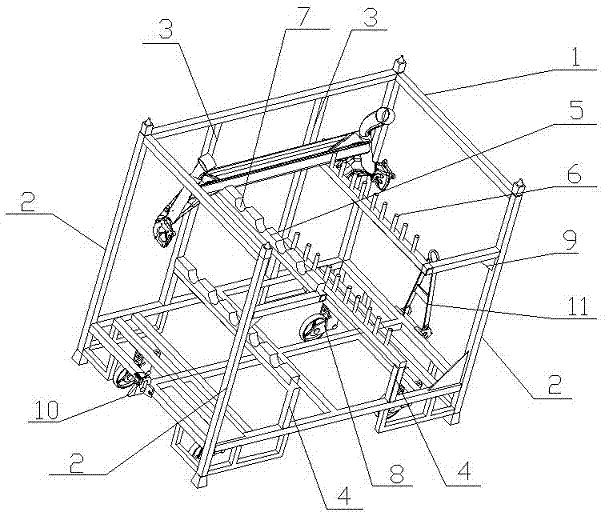
[0012] Such as figure 1 As shown, this embodiment provides a working station for a rear torsion beam of an automobile, including a frame 1, the frame 1 is supported by support rods 2 around, and the rear end surface of the frame 1 is symmetrically arranged with horizontal With the long support column 3 of the support rod 2, the front end surface of the frame 1 is symmetrically provided with the short support column 4 horizontally and the support rod 2, and the support rods 2 on both sides of the front end surface of the frame 1 are The upper end is provided with a short support column 4 perpendicular to its support rod 2, the long support column 3 and the short support column 4 at th...


PUM


Abstract

The invention discloses a working position apparatus for automobile rear torsion beams. Through the arrangement of limiting blocks and positioning rods, the automobile rear torsion beams can be easily placed in the clamping grooves of the limiting blocks and then fixed by the positioning rods, so that the rear torsion beams are prevented from being broken or falling down due to jolt in the transport process, and are protected very well in the transport or placement process so as not to be rejected. The working position apparatus provides a special apparatus for the automobile rear torsion beams, can protect the automobile rear torsion beams very well, is convenient and safe to operate and reduces the after cost.

Description

technical field [0001] The invention relates to the field of production and processing of automobile parts, in particular to a transportation device for placing rear torsion beams of automobiles. Background technique [0002] The rear torsion beam of the automobile is a main part of the rear chassis of the automobile, with a length of more than 1.4m. In industry, the requirements for the mounting holes on the rear torsion beam and the dimensional accuracy of the assembly surface are very high. At the same time, the requirements for the anti-corrosion performance of the electrophoretic coating are also very high. , so the surface of the rear torsion beam cannot be scratched or scratched, and the use of material boxes or storage cages in the traditional technology cannot guarantee the quality requirements for storage and transportation. It is inevitable that bumps and falls will occur during placement and movement, resulting in the generation of unqualified products. Therefore...

Claims


Application Information

Patent Timeline
Patent Type & Authority Applications(China)
IPC IPC(8): B65D61/00
Inventor 胡拥军陈存全陈昊
Owner WUHU POWER TECH
Why Eureka
Try Eureka