Yarn guide table

A platform and yarn technology, applied in the field of yarn-guided platforms, can solve problems such as production accidents, static electricity, and large friction, and achieve the effects of reducing costs, reducing static electricity, and reducing skeins

Inactive Publication Date: 2015-04-08
JIANGSU NIJIAXIANG GROUP WORSTED TEXTILE
View PDF0 Cites 2 Cited by
  • Summary
  • Abstract
  • Description
  • Claims
  • Application Information

AI Technical Summary

Problems solved by technology

[0002] The traditional yarn guiding platform is the proposed wooden comb structure, and there are only two rows, and the angle between the two rows is 90°. During the yarn guiding process, the friction force is relatively large, which will generate static electricity, cause fire, and cause production accident, unnecessary loss

Method used


Image

  • Yarn guide table
  • Yarn guide table
  • Yarn guide table

Examples


Embodiment Construction

[0012] All features disclosed in this specification, or steps in all methods or processes disclosed, may be combined in any manner, except for mutually exclusive features and / or steps.

[0013] Any feature disclosed in this specification (including any appended claims, abstract and drawings), unless expressly stated otherwise, may be replaced by alternative features which are equivalent or serve a similar purpose. That is, unless expressly stated otherwise, each feature is one example only of a series of equivalent or similar features.

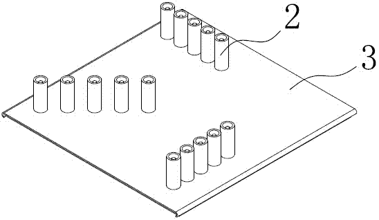
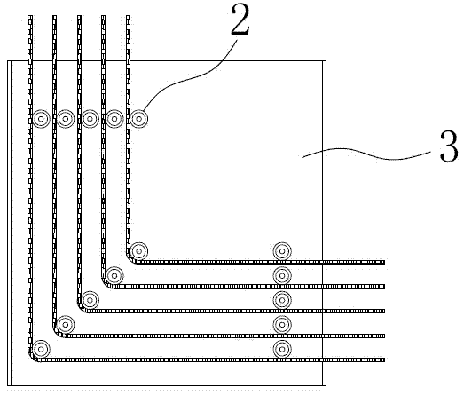
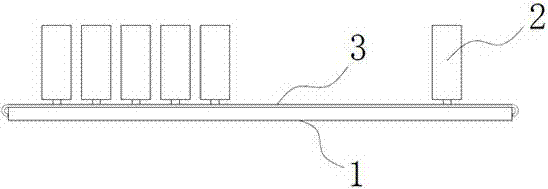
[0014] Such as figure 1 , figure 2 and image 3 A kind of yarn guiding platform shown comprises base plate 1, and described base plate 1 is provided with three rows of comb teeth 2, and the included angle between each row of comb teeth 2 is 45°, as Figure 4 As shown, the comb teeth 2 include a support column 2.1 and a rolling sleeve 2.2, and the rolling sleeve 2.2 and the support column 2.1 are connected to each other through bearings.

...


PUM


Abstract

The invention discloses a yarn guide table comprising a bottom plate. There rows of comb teeth are arranged on the bottom plate. Every two rows of comb teeth have an included angle of 45 degrees. Each comb tooth comprises a support post and a rolling sleeve; the rolling sleeve is connected with the support post through a bearing. The yarn guide table is reasonable in structural design, rolling action of the bearings helps decrease static electricity generated by friction of yarns, the reasonable arrangement of the comb teeth in each row helps decrease tangling of the yarns, productivity is improved, safety hazards are avoided, and cost is lowered.

Description

technical field [0001] The invention relates to the field of textile machinery, in particular to a yarn guiding platform. Background technique [0002] The traditional yarn guiding platform is the proposed wooden comb structure, and there are only two rows, and the angle between the two rows is 90°. During the yarn guiding process, the friction force is relatively large, which will generate static electricity, cause fire, and cause production Accidents and unnecessary losses. Contents of the invention [0003] In order to solve the problem of static electricity generated by the friction force of wooden comb teeth, the present invention provides a yarn guiding platform, which includes a bottom plate, and three rows of comb teeth are arranged on the bottom plate, and the included angle between each row of comb teeth is 45°, the comb teeth include a support column and a rolling sleeve, and the rolling sleeve and the support column are connected to each other through bearings...

Claims


Application Information

Patent Timeline
Patent Type & Authority Applications(China)
IPC IPC(8): B65H57/16
Inventor 杨毅方顾士清杨丽萍周东顾建丙
Owner JIANGSU NIJIAXIANG GROUP WORSTED TEXTILE
Why Eureka
Try Eureka