A falling film evaporation heat exchange device with flow phase change energy storage

A falling-film evaporation and heat exchange device technology, which is applied in the operation mode of machines, evaporators/condensers, machines using solar energy, etc. It is difficult to improve the efficiency and other problems, and achieves the effect of solving the large change rate of the phase change volume, solving the corrosiveness and high explosion limit.

Active Publication Date: 2016-12-28
HARBIN INST OF TECH
View PDF5 Cites 0 Cited by
  • Summary
  • Abstract
  • Description
  • Claims
  • Application Information

AI Technical Summary

Problems solved by technology

[0003] The present invention aims to solve the problem of large volume of accumulator in the system, equipment and method of the existing sleeve-type energy storage type multi-source heat pump integrated system, difficulty in improving heat exchange efficiency, constraints by the properties of energy storage materials, and two-way cooling / heating. Utilizing the problem of imbalance, a falling film evaporation heat exchange device with flow phase change energy storage is provided

Method used


Image

  • A falling film evaporation heat exchange device with flow phase change energy storage
  • A falling film evaporation heat exchange device with flow phase change energy storage
  • A falling film evaporation heat exchange device with flow phase change energy storage

Examples


specific Embodiment approach 1

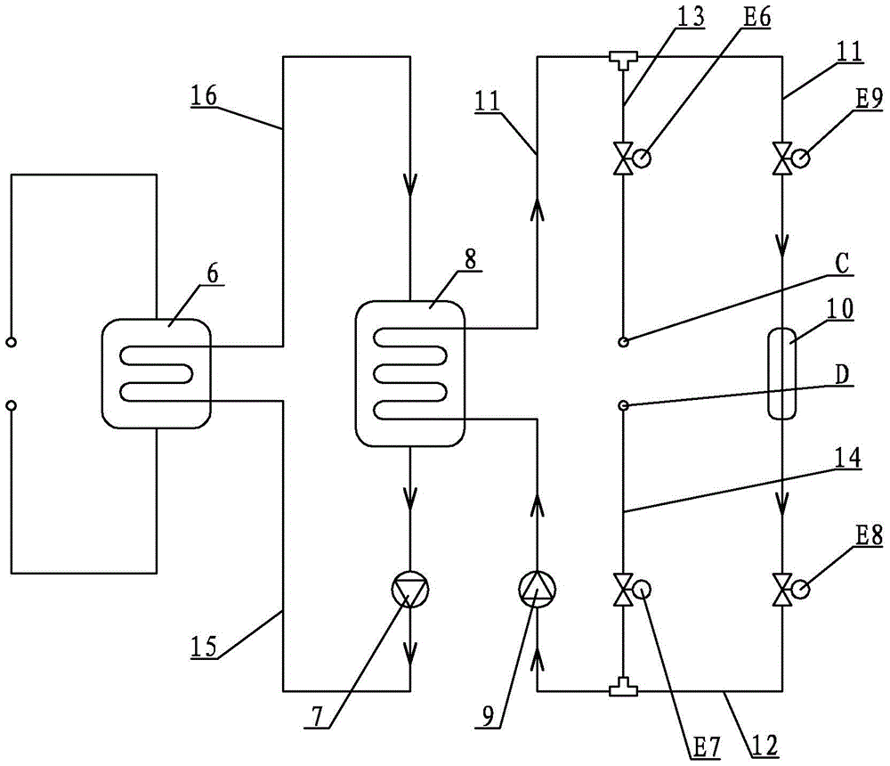
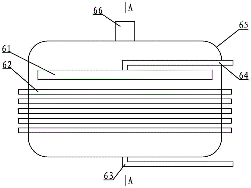
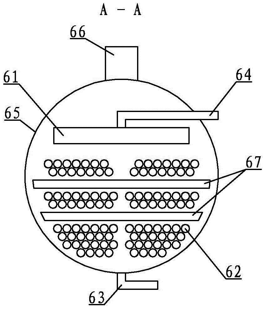
[0018] Specific embodiment one: combination Figure 1 ~ Figure 6 To illustrate this embodiment, this embodiment includes a falling film energy storage evaporator 6, a stainless steel magnetic pump 7, an energy storage tank 8, a water pump 9, a solar collector 10, a first solenoid valve E9, a second solenoid valve E8, and a second solenoid valve E8. Three solenoid valve E6, fourth solenoid valve E7, first pipe 11, second pipe 12, third pipe 13, fourth pipe 14, fifth pipe 15, and sixth pipe 16, falling film type The energy storage evaporator 6 is composed of a liquid distributor 61, an oil return pipe 63, a liquid supply pipe 64, an evaporator shell 65, two middle separators 67 and multiple sets of phase-change microemulsion outer surface strengthening tube bundles 62, and a liquid distributor 61 Horizontally arranged in the evaporator shell 65, one end of the liquid supply pipe 64 is connected with the liquid distributor 61, the other end of the liquid supply tube 64 leads to th...

specific Embodiment approach 2

[0019] Specific implementation manner two: combination Figure 5 To illustrate this embodiment, the phase transition temperature of the organic phase change microemulsion of this embodiment ranges from 4°C to 8°C. This temperature range enables the phase change energy storage material to have the dual functions of cold storage and heat supply, and the material is also liquid at room temperature and can be directly charged. The other components and connection relationships are the same as in the first embodiment.

specific Embodiment approach 3

[0020] Specific implementation mode three: combination Figure 5 To describe this embodiment, the phase transition temperature range of the organic phase change microemulsion of this embodiment is 6°C. This temperature makes the phase-change energy storage material have the dual functions of cold storage and heat supply, and the material is also liquid at room temperature and can be directly charged. Other components and connection relationships are the same as in the second embodiment.


PUM


Abstract

The invention relates to a flowing phase change and energy storage falling film evaporative heat exchange device. An inlet of a water pipe is connected with a pressing-out end of a water pump, an outlet of a water pipe is connected with an inlet of a solar heat collector through a first pipeline, an outlet of the solar heat collector is connected with a sucking-in opening of the water pump through a second pipeline, a first electromagnetic valve is arranged at the inlet end part of the solar heat collector, a second electromagnetic valve is arranged at the outer end part of the solar heat collector, a third electromagnetic valve is arranged on a third pipeline, a fourth electromagnetic valve is arranged on a fourth pipeline, the outlet end of a phase change microemulsion discharging pipe is connected with the sucking-in end of a stainless steel magnetic pump, an inlet of each of a plurality of groups of phase change microemulsion outer surface reinforcing pipe beams is communicated with one end of a fifth pipeline, the other end of the fifth pipeline is connected with the pressing-out end of the stainless steel magnetic pump, an outlet of each of the plurality of groups of phase change microemulsion outer surface reinforcing pipe beams is communicated with one end of a sixth pipeline, and the other end of the sixth pipeline is connected with a phase change microemulsion feeding pipe of an energy storage tank. The flowing phase change and energy storage falling film evaporative heat exchange device can be used in a solar-air energy coupling heat pump system.

Description

Technical field [0001] The invention relates to an energy storage heat exchange device for an energy storage heat pump system, in particular to a falling film evaporation heat exchange device for mobile phase change energy storage. Background technique [0002] At present, air source heat pumps have been widely used in various regions, but there is a problem of low heating efficiency in cold climate areas in the north, and frosting of the heat pump cycle outdoor heat exchanger in areas with high outdoor relative humidity. As a result, air source heat pump integrated systems combined with technologies in other fields have become a new development direction. Most integrated systems are still in the design stage, failing to make rational combinations of different types of technologies. In the existing energy storage heat pumps, most of the energy storage heat exchangers are of the tube-in-tube structure. The disadvantages are: 1) The tube-in-tube accumulator consumes a lot of metal ...

Claims


Application Information

Patent Timeline
Patent Type & Authority Patents(China)
IPC IPC(8): F25B39/00F24F5/00
CPCF25B27/002F25B29/00F25B39/00F25B41/20
Inventor 倪龙姚杨曲德虎
Owner HARBIN INST OF TECH
Why Eureka
Try Eureka