Liquid crystal display panel
A liquid crystal display panel and display area technology, applied in static indicators, nonlinear optics, instruments, etc., can solve the problems of different color mixing effects, different contrasts, color shifts, etc., so as to improve the color shift phenomenon and reduce the impedance difference. Effect
- Summary
- Abstract
- Description
- Claims
- Application Information
AI Technical Summary
Problems solved by technology
Method used
Image
Examples
Embodiment 1
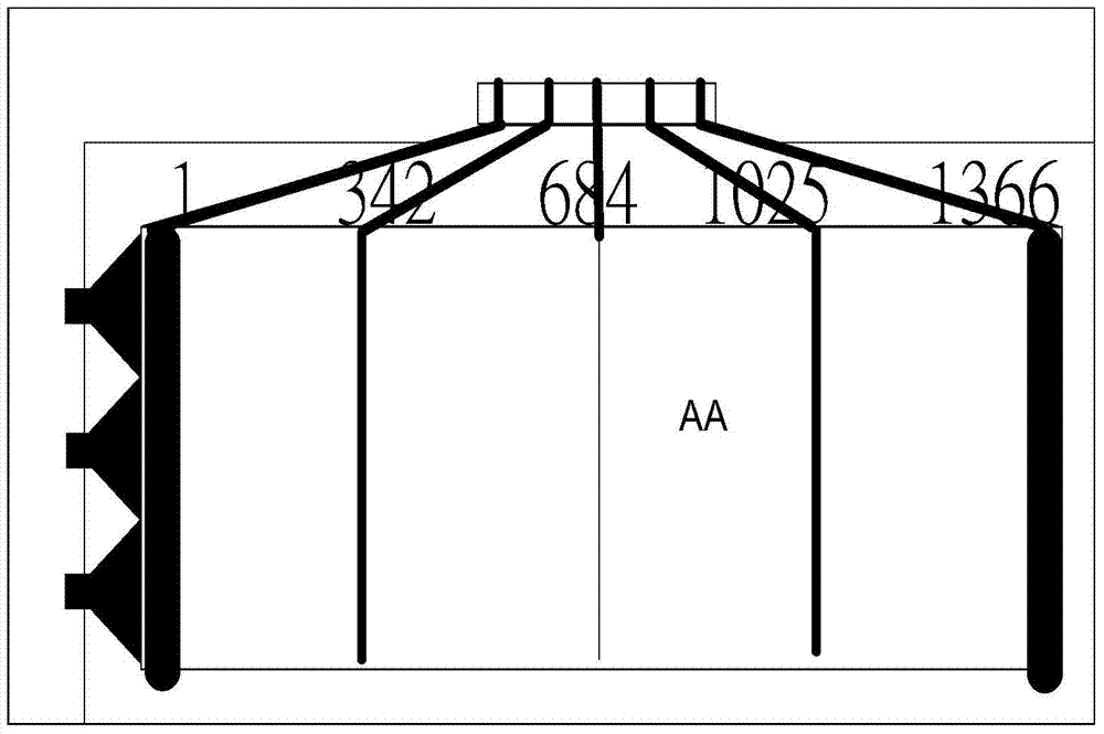
[0034] image 3 It is a specific embodiment of the present invention. In this embodiment, the line width of the data lines in the display area increases gradually along the direction from the center of the display area to the two sides of the display area. This situation is mainly for the situation that the data line Rfanout in the fan-out area is much smaller than Cfanout. In this case, as the width of the data line in the display area increases continuously, the resistance value Rdata of the data line will decrease accordingly. Although the capacitance Cdata of the data line in the display area will also increase accordingly, because the capacitance Cfanout of the data line in the fan-out area is relatively large, the change of (Cfanout+Cdata) is relatively small, and its effect on the delay time constant RCdelay Changes have little effect. On the whole, the delay time constant RCdelay of the data lines on both sides of the liquid crystal display panel will be reduced due...
Embodiment 2
[0037] Figure 4is another specific embodiment of the present invention. In this embodiment, the line width of the data lines in the display area decreases gradually along the direction from the center of the display area to the two sides of the display area. This situation is mainly for the situation that the data line Rfanout in the fan-out area is much larger than Cfanout. In this case, as the width of the data line in the display area decreases continuously, the capacitance Cdata of the data line will decrease accordingly. Although the resistance value Rdata of the data line in the display area will also increase accordingly, because the resistance Rfanout of the data line in the fan-out area is relatively large, the change of (Rfanout+Rdata) is relatively small, and its effect on the delay time constant RCdelay changes have little effect. On the whole, the delay time constant RCdelay of the data lines on both sides of the liquid crystal display panel will be reduced du...
Embodiment 3
[0040] Figure 5 It is the third specific embodiment proposed by the present invention. In this embodiment, the line widths of several data lines located on both sides of the display area are uniformly narrowed along the direction from the upper end of the display area to the lower end of the display area, while the line widths of several data lines located in the middle of the display area are narrowed along the direction from the upper end of the display area to the lower end of the display area. The direction from the upper end of the display area to the lower end of the display area becomes evenly wider. In this case, although the line width of the data lines located on both sides of the display area narrows evenly along the direction from the upper end of the display area to the lower end of the display area, the capacitance Cdata of the entire data line is almost unchanged. , but the increase of the resistance value Rdata gradually decreases with the increase of the len...
PUM
 Abstract
Description
Claims
Application Information
 - R&D
- Intellectual Property
- Life Sciences
- Materials
- Tech Scout
- Unparalleled Data Quality
- Higher Quality Content
- 60% Fewer Hallucinations
Browse by: Latest US Patents, China's latest patents, Technical Efficacy Thesaurus, Application Domain, Technology Topic, Popular Technical Reports.
© 2025 PatSnap. All rights reserved.Legal|Privacy policy|Modern Slavery Act Transparency Statement|Sitemap|About US| Contact US: help@patsnap.com


