
WSN (wireless sensor network) node positioning method based on RSS (Received Signal Strength) and distance measurement unbiased estimation

A technology of node positioning and bias estimation, applied in wireless communication, electrical components, etc., can solve the problems of inability to essentially eliminate ranging bias and insufficient analysis.

Inactive Publication Date: 2015-04-08
HARBIN INST OF TECH
View PDF2 Cites 12 Cited by
  • Summary
  • Abstract
  • Description
  • Claims
  • Application Information

AI Technical Summary

Problems solved by technology

[0005] The purpose of the present invention is to solve the problem that the WSN node positioning algorithm based on RSS ranging is affected by noise, which causes insufficient analysis of ranging errors, and cannot essentially eliminate the problem of ranging deviation caused by noise. WSN node location method based on RSS and ranging unbiased estimation

Method used

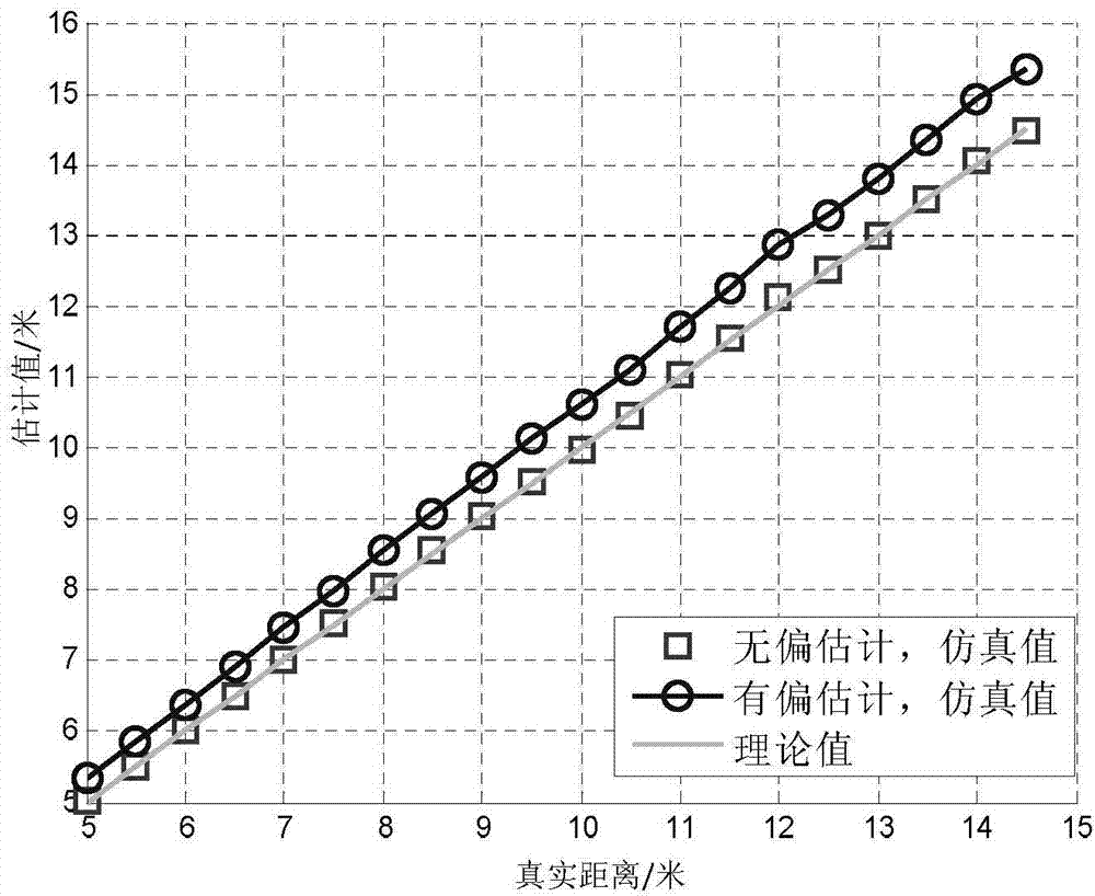
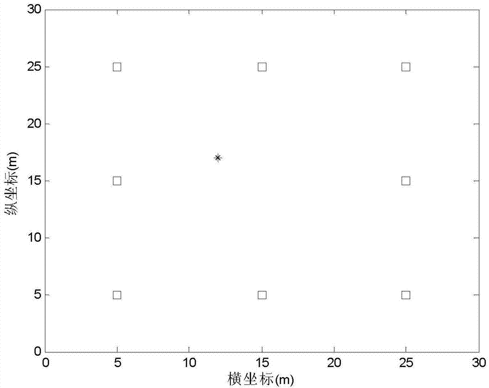
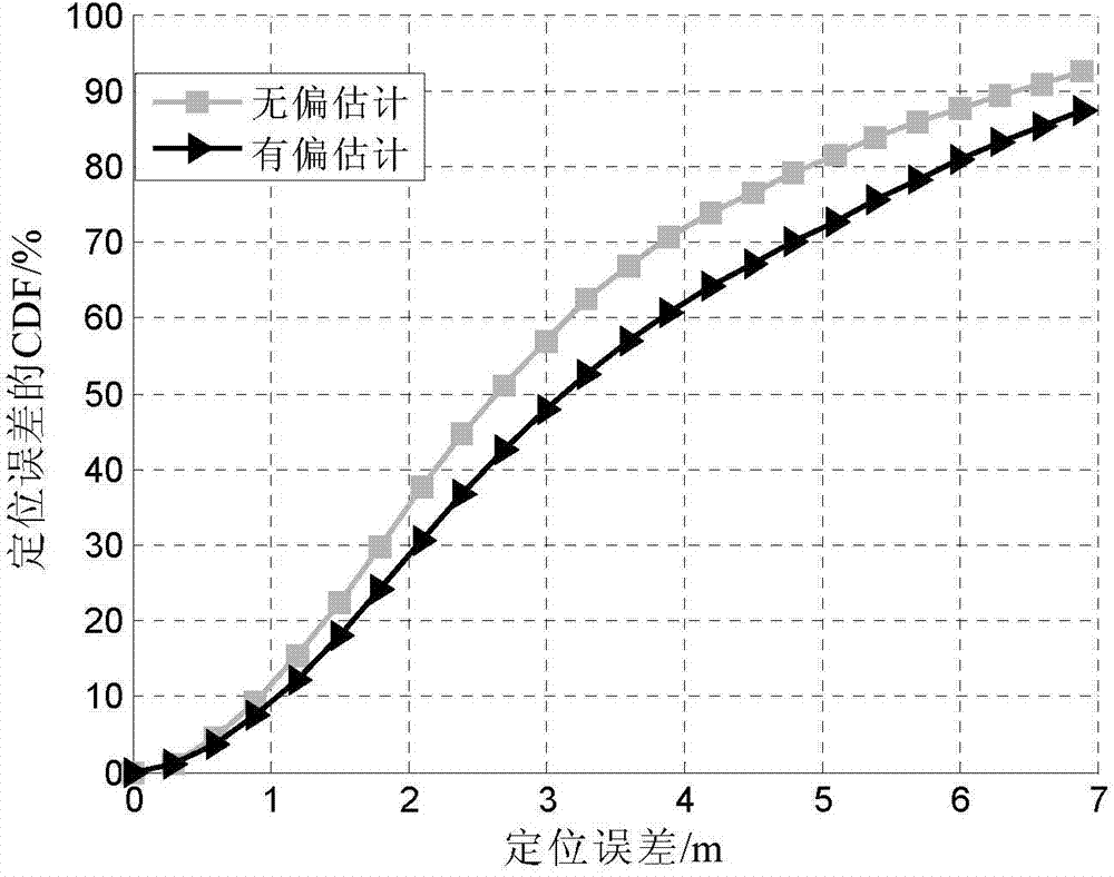

Image

  • WSN (wireless sensor network) node positioning method based on RSS (Received Signal Strength) and distance measurement unbiased estimation
  • WSN (wireless sensor network) node positioning method based on RSS (Received Signal Strength) and distance measurement unbiased estimation
  • WSN (wireless sensor network) node positioning method based on RSS (Received Signal Strength) and distance measurement unbiased estimation

Examples


specific Embodiment approach 1

[0031] Specific embodiment one: a kind of WSN node localization method based on RSS and ranging unbiased estimation of this embodiment, specifically is prepared according to the following steps:

[0032] Step 1. Pre-deploy M beacon nodes in the working environment of the sensor network; assume any unknown node U in the working environment of the sensor network = (x, y), and let U receive information from the beacon node B i The coordinates of the signal are x i ,y i , namely B i It is visible to the unknown node U, i=1, 2,..., N, N≤M; wherein, N represents the number of beacon nodes visible to the unknown node U;

[0033] Step 2. According to the general signal propagation model, calculate the distance between the unknown node and the beacon node B under the influence of Gaussian noise n i distance Among them, at the distance from the beacon node d 0 Set the reference node at , and the reference node receives the beacon node B i The signal power is P i (d 0 ); unknown...

specific Embodiment approach 2

[0052] Specific embodiment 2: The difference between this embodiment and specific embodiment 1 is that in step 2, according to the general signal propagation model, under the influence of noise n, the unknown node and the beacon node B i distance v i = 10 P i ( d 0 ) - P i ( d i ) - n 10 · α The specific process is:

[0053] P(d)=P(d 0 )-10αlg(d / d 0 ) (7)

[0054] Among them, d 0 is the distance f...

specific Embodiment approach 3

[0060] Specific implementation mode three: the difference between this implementation mode and specific implementation mode one or two is: in step three, v in step two i Perform an expectation analysis to get The specific process is:

[0061] Obtained according to formula (8),

[0062] lg v i = P i ( d 0 ) - P i ( d i ) - n 10 · α - - - ( 10 )

[0063] definition C = ...


PUM


Abstract

The invention relates to a node positioning method, in particular to a WSN (wireless sensor network) node positioning method based on RSS (Received Signal Strength) and distance measurement unbiased estimation. The WSN node positioning method based on the RSS and the distance measurement unbiased estimation solves the problems that a WSN node positioning algorithm based on RSS distance measurement is influenced by noise, and thereby can not fully analyze distance measurement error, and furthermore can not essentially eliminate distance measurement deviation caused by the noise. The WSN node positioning method based on the RSS and the distance measurement unbiased estimation includes steps: 1, setting an unknown node U=(x, y), and setting a coordinate of a signal from a beacon node Bi as (xi, yi); 2, calculating the distance vi between the unknown node and the beacon node Bi; 3, obtaining unbiased estimator; 4, calculating the distance between the unknown node U and the beacon node Bi; 5, using a Newton iteration method to solve the position (x, y) of the unknown node U; 6, obtaining delta X7, and obtaining positioned positions xk and yk of the unknown node and the like. The WSN node positioning method based on the RSS and the distance measurement unbiased estimation is used in the node positioning field.

Description

technical field [0001] The invention relates to a node positioning method, in particular to a WSN node positioning method based on RSS and distance measurement unbiased estimation. Background technique [0002] A wireless sensor network (Wireless Sensor Network, WSN) is a network composed of a large number of sensor nodes with sensing, computing and wireless communication capabilities. A large number of sensor nodes cooperate with each other to complete specific tasks. In many cases, accurate node location information needs to be known. However, a large number of sensor nodes are often deployed randomly, and it is not advisable to obtain the location information of each node by manpower. In addition, in order to meet the needs of industrial applications, sensor nodes are generally relatively cheap, and it is impossible to configure each node with a positioning module (such as a GPS module) for positioning. Therefore, it is necessary to obtain the location information of W...

Claims


Application Information

Patent Timeline
IPC IPC(8): H04W64/00
CPCH04W64/00H04W64/006
Inventor 孟维晓岳晋韩帅巩紫君张德坤
Owner HARBIN INST OF TECH
Learn More