Welding tool used for double-acting type friction stir welding or double-acting type friction stir spot welding, and welding device using same

A jointing tool and friction stir technology, which is applied in the direction of manufacturing tools, welding equipment, metal processing equipment, etc., can solve the problems such as the joint tool cannot move forward and backward smoothly, and the movement is bad, so as to achieve the effect of effective joint and quality improvement

Active Publication Date: 2015-04-08
KAWASAKI HEAVY IND LTD
View PDF12 Cites 14 Cited by
  • Summary
  • Abstract
  • Description
  • Claims
  • Application Information

AI Technical Summary

Problems solved by technology

[0004] However, it is known that in double-action friction stir welding or double-action friction stir point joining (hereinafter, double-action friction stir welding or double-action friction stir point joints are collectively referred to as "double-action friction stir welding"), because Malfunctions due to entry of the object to be joined or sticky matter overflowing from the object to be joined (hereinafter referred to as "joint object, etc.") between the pin member and the shoulder member
In addition, it is known that an object to be joined is similarly inserted between the shoulder member and the clamping member, resulting in malfunction.
Specifically, entry of objects to be bonded or the like is likely to occur due to the pressing and pulling out of the bonding tools, and when the objects to be bonded that entered enter between the pin member and the shoulder member, they will stick to the joints of these bonding tools. surface (for example, in the case of a pin member, on the outer peripheral surface, in the case of a shoulder member, on the inner peripheral surface), there is a possibility that the forward and backward movement of the joining tool may not be performed smoothly

Method used


Image

  • Welding tool used for double-acting type friction stir welding or double-acting type friction stir spot welding, and welding device using same
  • Welding tool used for double-acting type friction stir welding or double-acting type friction stir spot welding, and welding device using same
  • Welding tool used for double-acting type friction stir welding or double-acting type friction stir spot welding, and welding device using same

Examples


Embodiment 1)

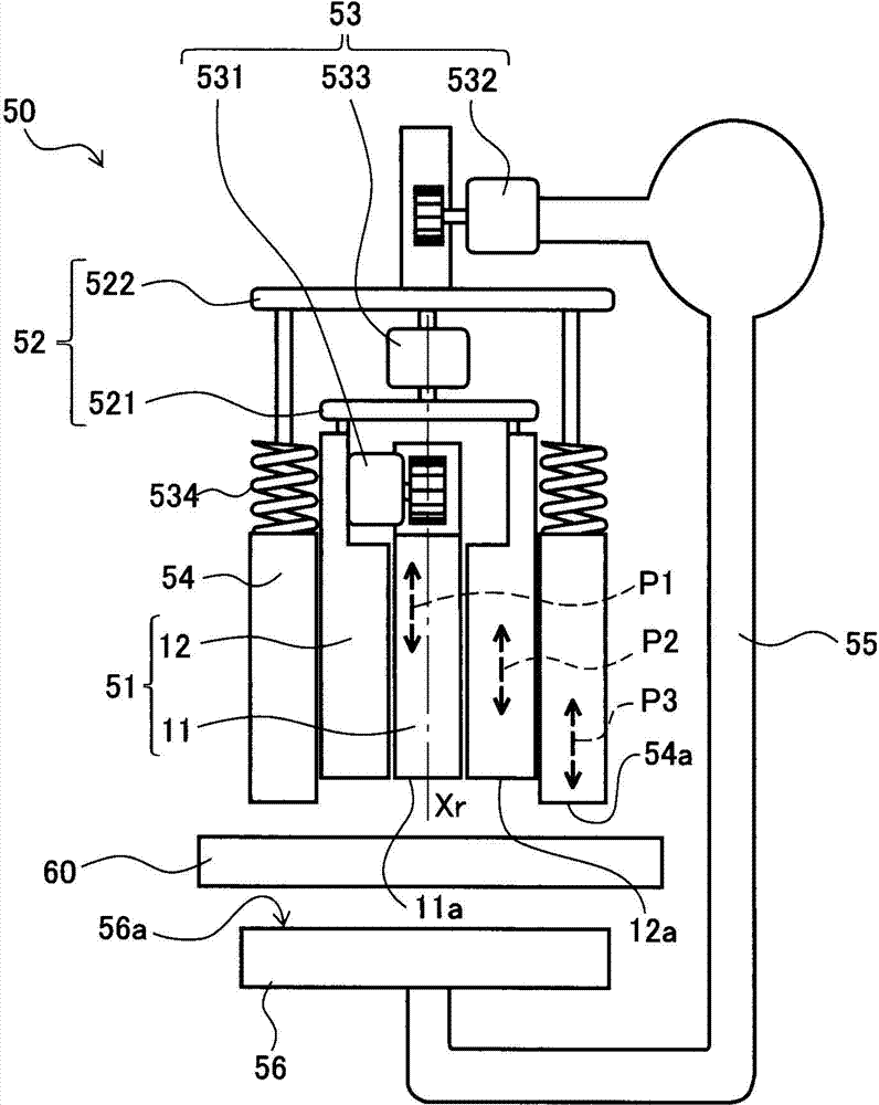
[0109]First, as the friction stir welding device 50, a double-action FSJ manipulator system manufactured by Kawasaki Heavy Industries, Ltd. was used, and as the rotary tool 51, a pin member 11 coated with hydrogen-free DLC was used as the rotary tool 51, and the pin member 11 was made to move forward and backward. It accommodates a cylindrical shoulder member 12 whose entirety is coated with hydrogen-free DLC except the abutting surface 12 a , and a cylindrical holding member 54 located outside the shoulder member 12 . In this rotary tool 51 , the outer diameter of the portion (the pin member 11 and the shoulder member 12 ) that moves forward and backward relative to the workpiece 60 is 6 mm, and the outer diameter of the clamping member 54 that accommodates the portion that moves forward and backward is 6 mm. is 12mm.

[0110] Next, as the object 60 to be joined, a member in which an aluminum material (AL6061-T6) with a thickness of 0.025 inches (approximately 0.635 mm) and a...

Embodiment 2)

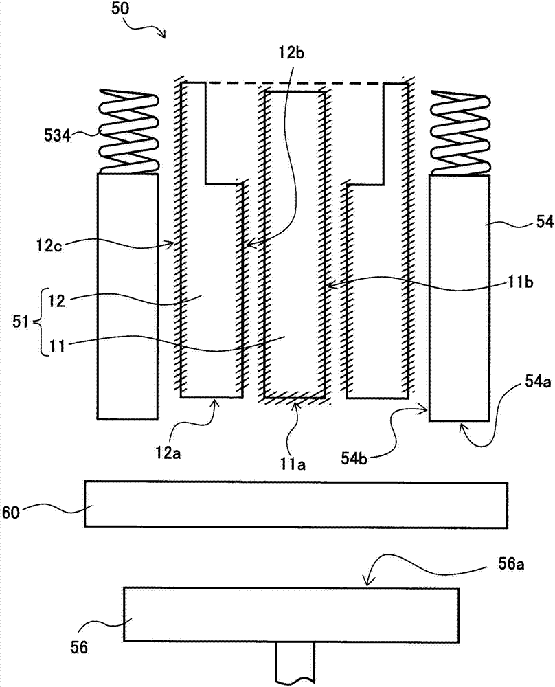
[0117] As the rotary tool 51 , a pin member 11 with an outer diameter of 3.0 mm, a shoulder member 12 with an outer diameter of 6.0 mm and an inner diameter of 3.03 mm, and a clamp member 54 with an outer diameter of 12 mm and an inner diameter of 6.03 mm were prepared. In addition, hydrogen-free DLC coating was performed on the pin member 11 , the shoulder member 12 , and the clamp member 54 .

[0118] In this structure, the gap between the pin member 11 and the shoulder member 12 is set so that the difference between the outer diameter of the pin and the inner diameter of the shoulder reaches 0.03mm, and the gap between the shoulder member 12 and the clamping member 54 is set to the outer diameter of the shoulder. The difference from the inner diameter of the clamping member reaches 0.03 mm. Using this rotary tool 51 , the object 60 to be joined was joined 30 times in the same manner as in the first embodiment described above.

[0119] When checking the joint of the object ...

reference example 1

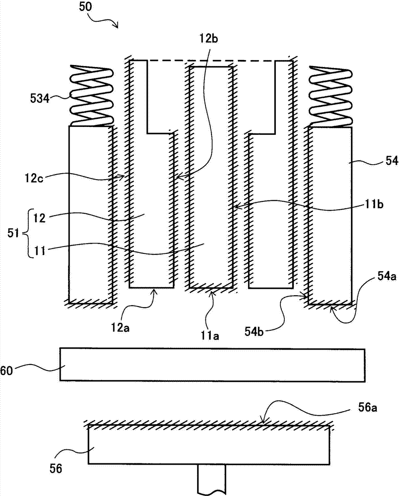
[0124] In the rotary tool 51, as the shoulder member 12, a member with an outer diameter of 6.0 mm and an inner diameter of 3.05 mm is used, and as the clamping member 54, a member with an outer diameter of 12 mm and an inner diameter of 6.05 mm is used. In Example 2, the to-be-joined object 60 was joined similarly.

[0125] In addition, in this structure, the clearance between the pin member 11 and the shoulder member 12 is set so that the difference between the outer diameter of the pin and the inner diameter of the shoulder is 0.05 mm, and the clearance between the shoulder member 12 and the clamping member 54 is set as the axis The difference between the outer diameter of the shoulder and the inner diameter of the holding member is set to be 0.05 mm.

[0126] When checking the joint of the object to be joined 60 after construction, no major problem in appearance was observed in either the contact portion of the pin member 11 or the contact portion of the shoulder member 12...


PUM

PropertyMeasurementUnit
thicknessaaaaaaaaaa

Abstract

This double-acting type friction stir welding tool is configured from at least a columnar pin member (11), and a shoulder member (12) which has a cylindrical shape located outside the pin member (11) and rotates around the same axis as the pin member (11). In the pin member (11), a contact surface (11a) with an object to be welded (60) and an outer peripheral surface (11b) have non-affinity for the object to be welded (60). In the shoulder member (12), an inner peripheral surface (12b) facing the pin member (11) and an outer peripheral surface (12c) have non-affinity for the object to be welded (60), and only a contact surface (12a) with the object to be welded (60) has affinity for the object to be welded (60). Further, the clearance between the pin member (11) and the shoulder member (12) can be made suitable.

Description

technical field [0001] The present invention relates to a joining tool used in double-action friction stir welding or double-action friction stir point joining and a joining device using the joining tool, and particularly relates to a joining tool capable of achieving good joining of objects to be joined and using the joining tool Engaging device for engaging tools. Background technique [0002] Friction stir welding is a method in which a cylindrical pin member as a rotating tool is pushed (pressed) into an object to be joined made of a metal material, and the metal material is softened and stirred to join the objects to be joined to each other. This method is attracting attention as a joining technique that requires less heat input during joining and less softening or deformation. [0003] In addition, there is known a double-action friction stir welding in which a substantially cylindrical shoulder member having a hollow portion for inserting the pin member is used as a ...

Claims


Application Information

Patent Timeline
Patent Type & Authority Applications(China)
IPC IPC(8): B23K20/12
CPCB23K20/1255B23K20/1245
Inventor 冈田豪生
Owner KAWASAKI HEAVY IND LTD
Why Eureka
Try Eureka