High-pressure pump for internal combustion engines

A technology of high-pressure pumps and internal combustion engines, applied in fuel injection pumps, mechanical equipment, engine components, etc., can solve problems such as power loss and high current, and achieve the effect of reducing energy consumption and control energy

Inactive Publication Date: 2015-04-08
ROBERT BOSCH GMBH
View PDF5 Cites 0 Cited by
  • Summary
  • Abstract
  • Description
  • Claims
  • Application Information

AI Technical Summary

Problems solved by technology

Precisely at high spring preloads for high closing dynamics, correspondingly strong magnetic fields are required, which bring high currents and thus high power losses
Therefore, in the known solution a large control energy is generated, since the inlet valve has to be kept open during the entire suction phase

Method used


Image

  • High-pressure pump for internal combustion engines
  • High-pressure pump for internal combustion engines
  • High-pressure pump for internal combustion engines

Examples


Embodiment Construction

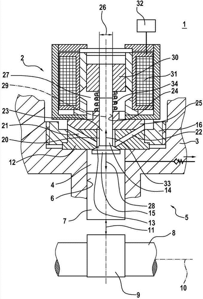
[0017] figure 1 A high-pressure pump 1 according to an exemplary embodiment of the invention is shown in a partially schematic sectional view. In particular, the high-pressure pump 1 can be designed as a radial piston pump or as a series piston pump. The high-pressure pump 1 is particularly suitable as a fuel pump for a fuel injection system of an air-compressed, self-igniting internal combustion engine. The high-pressure pump 1 has a suction valve 2 . The suction valve 2 is particularly suitable for use in such a high-pressure pump 1 . However, the suction valve 2 according to the invention is also suitable for other applications with correspondingly adapted changes.

[0018] A preferred application of the high-pressure pump 1 and the suction valve 2 is in a fuel injection system having a fuel distribution rail which stores diesel fuel under high pressure. However, other suitable fluids, ie other fluids as fuel, can also be controlled by the intake valve 2 and delivered b...


PUM


Abstract

The invention relates to a suction valve (2) which is used for a high-pressure pump (1), which is used in particular for air-compressing, self-igniting internal combustion engines. The suction valve (2) comprises a valve closing body (15), which interacts with a sealing seat (13), and an armature (30), which can be magnetically actuated and which is connected to the valve closing body (15). A pressure stage is provided, by means of which the valve closing body (15) can be loaded in an opening direction (28). Furthermore, the armature (30) can be magnetically actuated in such a way that the valve closing body (15) can be loaded against the sealing seat (13) in the closing direction (33) by a magnetic closing force by means of the armature (30). Furthermore, a high-pressure pump (1) having such a suction valve (2) is specified. By means of this embodiment, the activation energy for the suction valve (2) can be reduced.

Description

technical field [0001] The invention relates to a suction valve for a high-pressure pump, in particular for an air-compressing, self-igniting internal combustion engine, and to a high-pressure pump, in particular a radial piston pump or a serial piston pump. However, the high-pressure pump can also be used as a piston pump for conveying other suitable liquids. Background technique [0002] A high-pressure pump is known from DE 10 2010 027 745 A1, which is used in particular as a radial piston pump or a serial piston pump for a fuel injection system of an air-compressed, self-igniting internal combustion engine. An inlet valve is provided here, via which the fuel can be metered into the pump working chamber. A complete filling of the pump working chamber can be achieved here. However, it is also possible to partially fill the working chamber of the pump by appropriately controlling the inlet valve. Manipulation is achieved by energizing the solenoid coil. In this case, in...

Claims


Application Information

Patent Timeline
Patent Type & Authority Applications(China)
IPC IPC(8): F02M59/36F02D41/24F02D41/20
CPCF02D41/3845F02D41/20F02M59/368
Inventor F·波奇恩
Owner ROBERT BOSCH GMBH
Why Eureka
Try Eureka