

System and method for valve seat injection
A valve seat and valve technology, which is applied in the direction of charging system, fuel injection device, fuel injection control, etc., can solve the problems of engine packaging, high cost of engine, and increase of engine outline, etc.
- Summary
- Abstract
- Description
- Claims
- Application Information
AI Technical Summary
Problems solved by technology
Method used
Image

Examples
Embodiment Construction
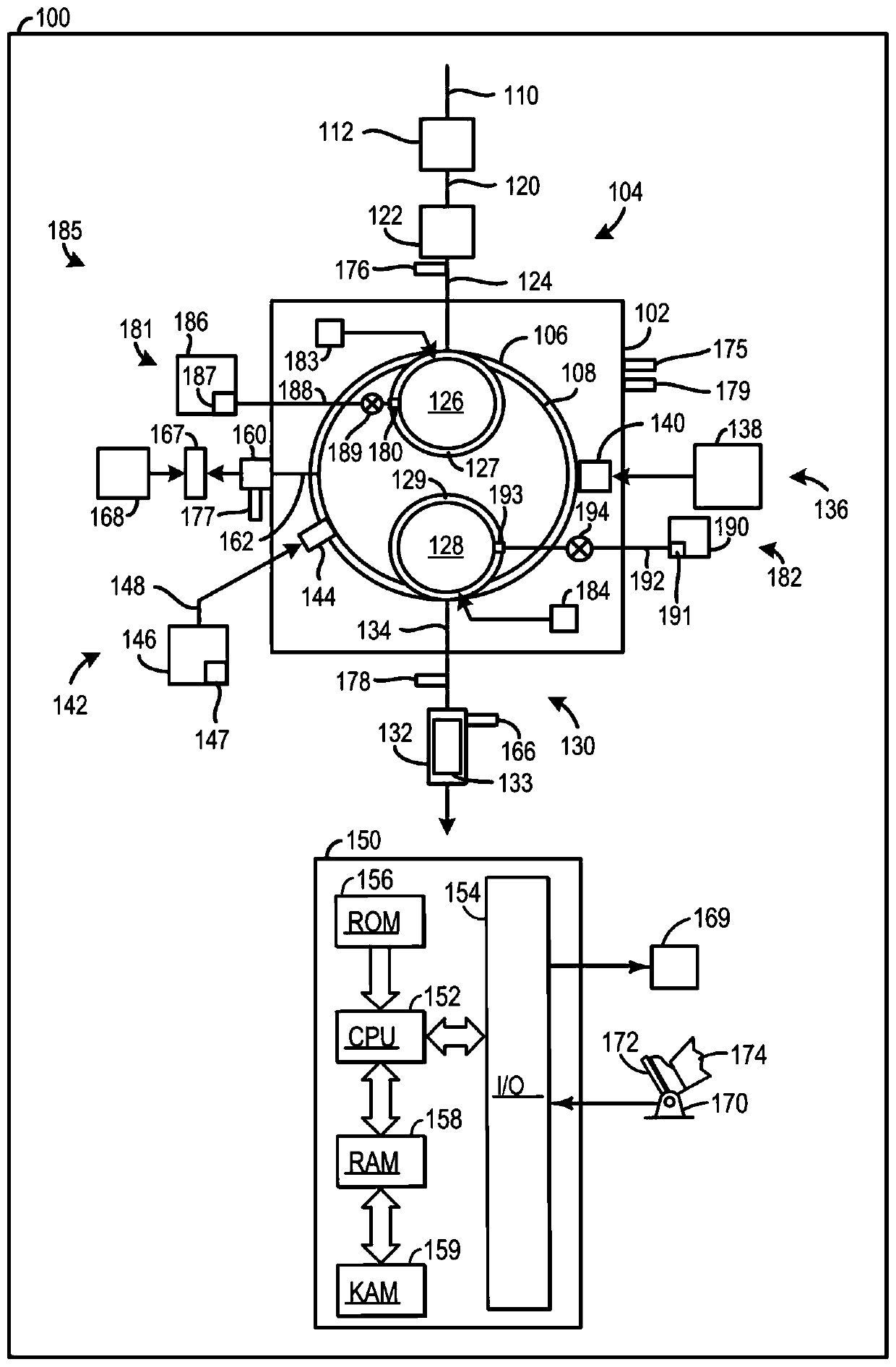
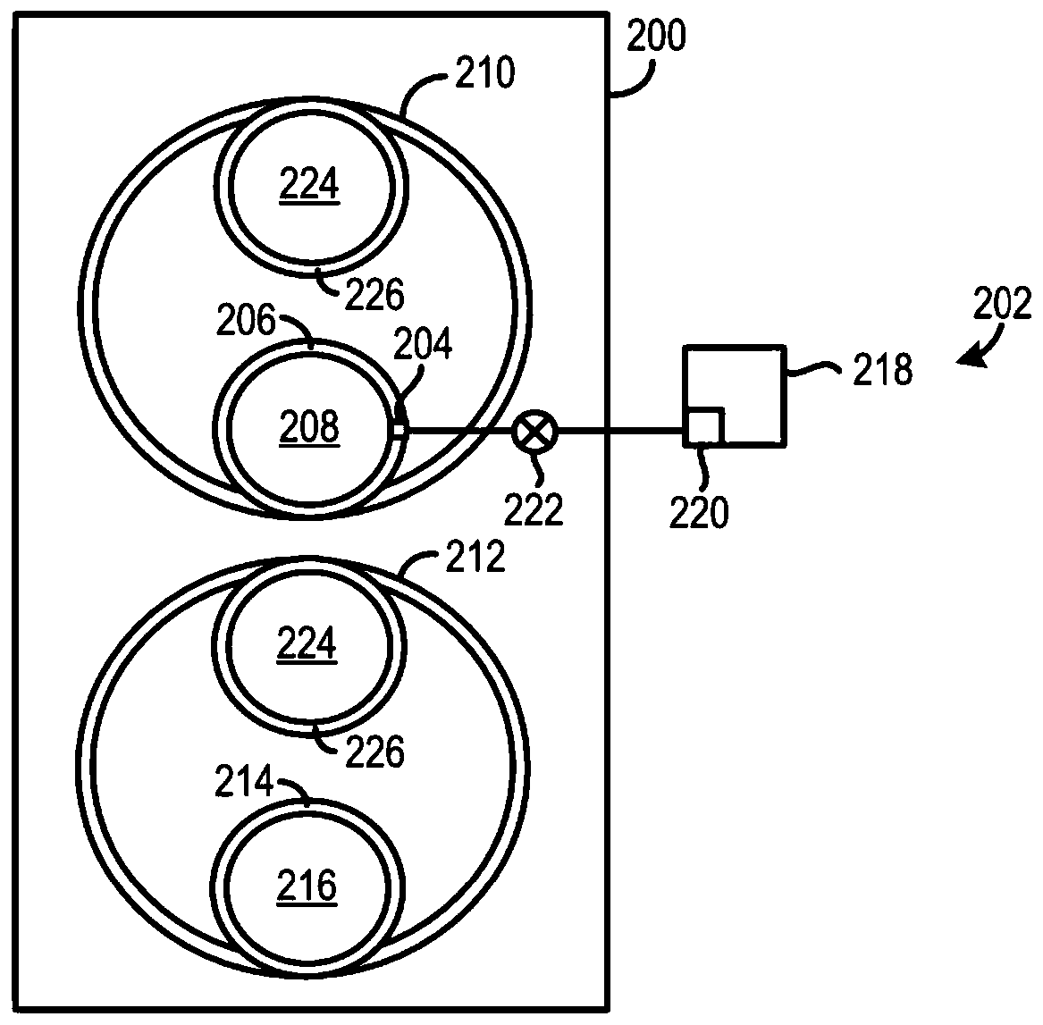
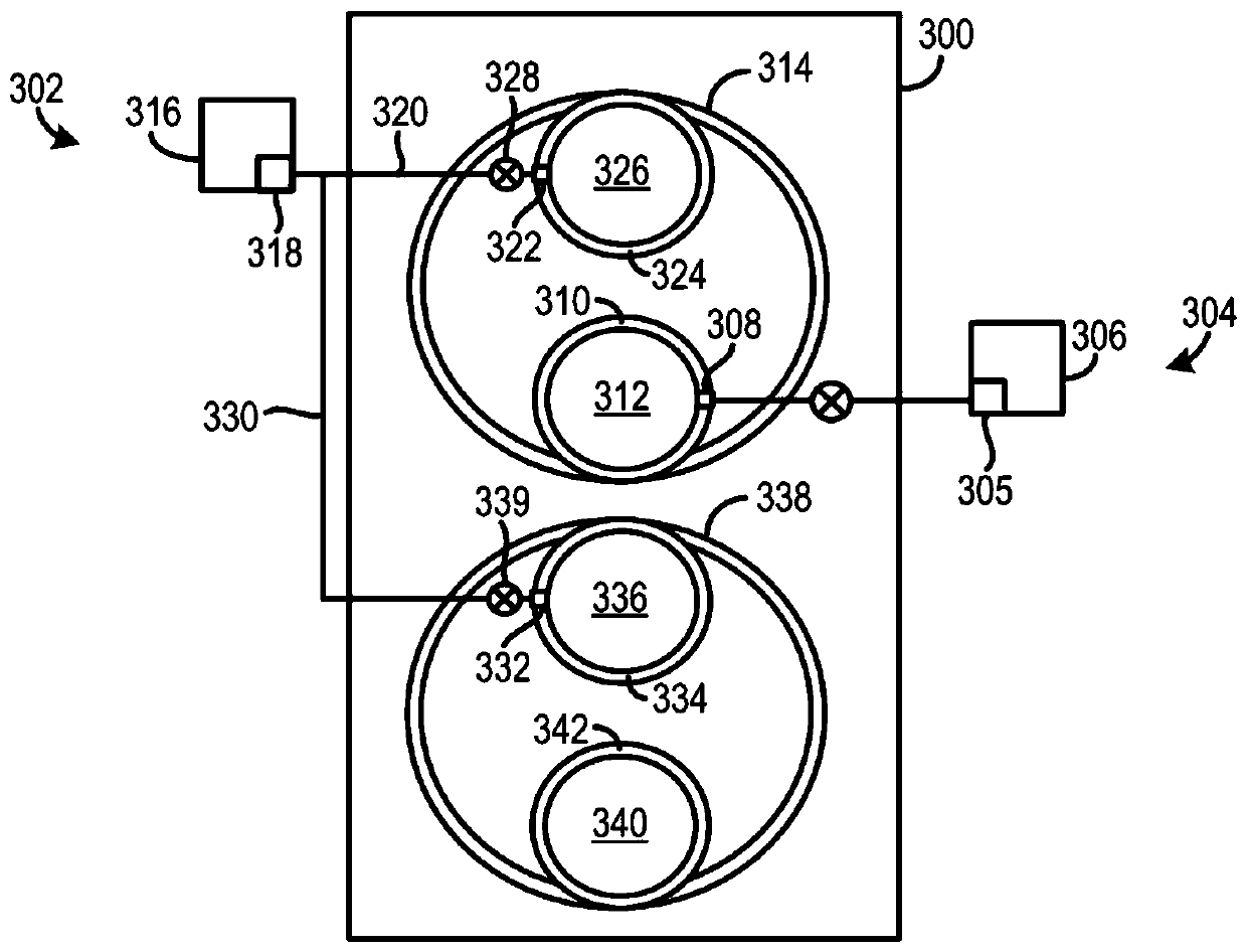
[0019] The following description relates to systems and methods for achieving fluid injection through an orifice in a valve seat. The valve seat fluid delivery assembly is used to direct fluid to the valve seat injection orifice. The fluid delivery assembly may include a fluid reservoir that stores fluid. When the injection orifice is included in the intake valve seat, the fluid may be alcohol, water, petroleum-based fuel, combinations thereof, and the like. In this way, the injection orifice can be operated to improve combustion efficiency, if desired. Conversely, when the injection orifice is included in the exhaust valve seat, the fluid may be exhaust fluid, air, combinations thereof, or the like. In this way, the injection orifice can be operated to reduce emissions, if desired.
[0020] A pump may also be included in the fluid delivery assembly and designed to generate fluid flow from the reservoir to the valve seat injection orifice. The position of the valve head de...
PUM
 Abstract
Description
Claims
Application Information