Method and apparatus for a dual mode burner yielding low NOx emission

A technology of burners and combustion chambers, applied in the direction of combustion methods, burners, gas fuel burners, etc.

Inactive Publication Date: 2015-04-08
ECLIPSE
View PDF5 Cites 3 Cited by
  • Summary
  • Abstract
  • Description
  • Claims
  • Application Information

AI Technical Summary

Problems solved by technology

However, there are still issue...

Method used


Image

  • Method and apparatus for a dual mode burner yielding low NOx emission
  • Method and apparatus for a dual mode burner yielding low NOx emission
  • Method and apparatus for a dual mode burner yielding low NOx emission

Examples


Embodiment Construction

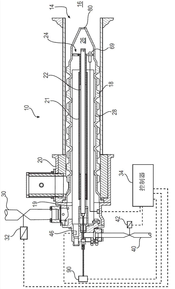
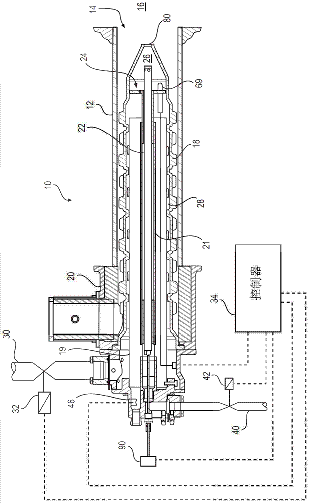
[0018] Reference will now be made to the drawings in which like elements are denoted by like reference numerals in the different drawings. figure 1 A burner 10 is shown comprising a generally hollow tubular cover tube 12 having an open end 14 which projects into a furnace / radiant tube 16 or other environment to be heated. By way of example only, the burners 10 may extend into closed radiant heating tubes or the like well known to those skilled in the art for indirect heating of the fire while avoiding substantial introduction of combustion products into the fire. As another example, the burner 10 may extend into the fire to provide direct heat to the fire while simultaneously introducing a bulk of the products of combustion into the fire. In the illustrated embodiment, the cover tube 12 is disposed around a hollow heat exchanger 18 made of ceramic or the like, having a surface of revolution extending outwardly from the shell 20 . The heat exchanger 18 may surround an air shro...


PUM


Abstract

A method and apparatus for a burner adapted to heat a furnace or other environment of use. In particular, a burner for providing a fuel gas in combination with an oxidant to effect controlled reaction of the fuel gas in a manner to reduce NOx emissions is described. Combustion of the fuel gas is shifted from the burner combustor to a location outside the burner once the temperature within the furnace/radiant tube has reached a sufficient level to complete combustion of the fuel gas.

Description

[0001] Cross References to Related Applications [0002] This application claims the benefit of US Provisional Patent Application No. 61 / 619,771 filed April 3, 2012, which is hereby incorporated by reference in its entirety. Background technique [0003] The use of high velocity gas burners is well known. In this type of burner, combustible gas and oxidant are mixed and ignited inside the burner. The resulting hot combustion gases then flow at high velocity through the outlet, into a furnace chamber for direct heating, or into radiant tubes for indirect heating. Combustion of the combustible gas and oxidant causes the ambient temperature inside the burner to increase significantly. To improve system efficiency, the oxidant can be preheated to generate higher temperatures. Preheating of the oxidant can be achieved through the use of a recuperative or regenerative system that uses waste heat from the exhaust gas. This high temperature combustion environment presents two chal...

Claims


Application Information

Patent Timeline
IPC IPC(8): F23D14/00
CPCF23N5/00F23C5/08F23D14/66F23C3/002F23C2900/03005F23D14/00F23D14/46F23C2900/99001Y02E20/34
Inventor 洪建辉J·W·惠勒
Owner ECLIPSE
Why Eureka
Try Eureka