Eureka AIR delivers breakthrough ideas for toughest innovation challenges, trusted by R&D personnel around the world.

Pellet low-nitrogen central burner and gas supply structure thereof

A central burner and pellet technology, applied in the direction of burner, combustion method, combustion type, etc., can solve the problems of environmental pollution, poor adaptability of coal quality, high nitrogen oxide content, etc.

Pending Publication Date: 2020-10-20
襄阳中和机电技术有限公司
View PDF0 Cites 0 Cited by
  • Summary
  • Abstract
  • Description
  • Claims
  • Application Information

AI Technical Summary

Problems solved by technology

[0002] The pellet low-nitrogen central burner for rotary kiln has developed from the single-channel pellet central burner in the early 1970s to the double-channel, three-channel pulverized coal burner, and later the four-channel burner. development, but its basic structure has been stuck in the old style, and there are certain limitations, including poor adaptability to coal quality, poor flame adjustment performance, few adjustment methods, insufficient combustion, etc. The existence of the above problems leads to the inability of the burner performance. To achieve the best, the content of nitrogen oxides produced after combustion is high, causing serious environmental pollution, and as modern production has stricter requirements on production quality, equipment performance and pollutant emissions in the production process, it is necessary to The burner structure is improved so that it can meet the needs of modern enterprise application production

Method used


Image

  • Pellet low-nitrogen central burner and gas supply structure thereof
  • Pellet low-nitrogen central burner and gas supply structure thereof
  • Pellet low-nitrogen central burner and gas supply structure thereof

Examples


Embodiment Construction

[0027] The invention will be described in detail below in conjunction with specific embodiments.

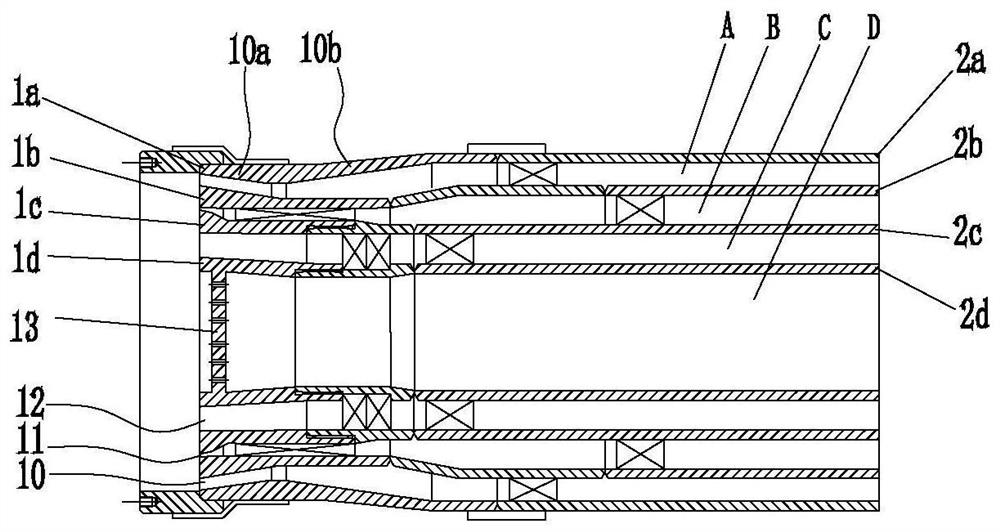
[0028] A pellet low-nitrogen central burner of the present invention includes a burner and an air guide pipe group connected to the burner; wherein the burner is mainly used to form a swirling flow of the combustion gas speed difference, and ensure the central air through the burner structure to achieve stable The flame effect improves the shape of the combustion flame, making it more complete and stable without fluctuations, and avoiding the phenomenon of sweeping the kiln lining. The air guide assembly is used to connect the gas supply system and the burner, and at the same time realize the adjustment of the gas flow and characteristics in the burner, so as to quickly adjust the strength and shape of the combustion flame, improve the performance of the burner, and ensure the burner at high temperature. Stability of structure and performance.

[0029] Such as figure 1 As shown...


PUM


Abstract

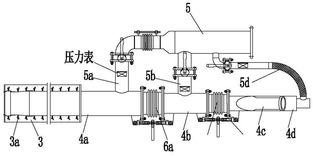
The invention belongs to the technical field of rotary kiln burners and accessories thereof, and particularly relates to a pellet low-nitrogen central burner and a gas supply structure thereof. The pellet low-nitrogen central burner comprises a burner and a guide duct group connected with the burner, wherein the burner consists of a plurality of barrel structures which are sleeved coaxially, including an axial flow wind barrel, a rotational flow wind barrel, a coal wind barrel and a central barrel in sequence; and a guide duct assembly consists of a plurality of circular pipes which are sleeved coaxially, including an axial flow wind pipe, a rotational flow wind pipe, a coal wind pipe and a central wind pipe. The gas supply structure comprises a protective structure arranged on the outer side of the pellet low-nitrogen central burner, a gas guide pipe group arranged on the back side of the pellet low-nitrogen central burner, and a gas supply pipe group. According to the pellet low-nitrogen central burner disclosed by the invention, the shape of burning flame is regular and complete by means of large speed difference, strong rotational flow and central wind flame stabilizing effect;the flame is stable without fluctuation; and the phenomenon of kiln lining sweeping is avoided.

Description

technical field [0001] The invention belongs to the technical field of a rotary kiln burner and its accessory structure, and in particular relates to a pellet low-nitrogen central burner and its gas supply structure. Background technique [0002] The pellet low-nitrogen central burner for rotary kiln has developed from the single-channel pellet central burner in the early 1970s to the double-channel, three-channel pulverized coal burner, and later the four-channel burner. development, but its basic structure has been stuck in the old style, and there are certain limitations, including poor adaptability to coal quality, poor flame adjustment performance, few adjustment methods, insufficient combustion, etc. The existence of the above problems leads to the inability of the burner performance. To achieve the best, the content of nitrogen oxides produced after combustion is high, causing serious environmental pollution, and as modern production has stricter requirements on produ...

Claims


Application Information

Patent Timeline
IPC IPC(8): F23D1/02
CPCF23D1/02
Inventor 吴敬
Owner 襄阳中和机电技术有限公司
Why Eureka
Eureka Blog
Learn More