
Construction machine

A technology for construction machinery and body, applied in construction, cranes, earthmoving machines/shovels, etc., can solve problems such as high manufacturing costs, fatigue, boom tipping, etc., to suppress the tipping of construction machinery, reduce fatigue, Operational safety effect

Inactive Publication Date: 2015-04-15
DAIKIN IND LTD
View PDF5 Cites 3 Cited by
  • Summary
  • Abstract
  • Description
  • Claims
  • Application Information

AI Technical Summary

Problems solved by technology

[0007] However, according to the above-mentioned conventional construction machine, when the dumping condition is met on a sloping ground, only the speed of the revolving body is decelerated. Therefore, there is a problem that even if the speed of the revolving body is decelerated, it may occur due to the movement of the boom. dump
[0008] Therefore, according to the above-mentioned conventional construction machine, there is such a problem that the operator must pay close attention to control the position and speed of the boom, which is quite tiring.
[0009] In addition, according to the above-mentioned conventional construction machine, since it is necessary to calculate the static dumping moment and the dynamic dumping moment based on the outputs of the inclination angle sensor of the body, the rotation angle sensor of the revolving body, the boom rotation angle sensor, and the arm rotation angle sensor to control the proportional solenoid valve, so there is such a problem that the control and structure become complicated and the manufacturing cost becomes high

Method used


Image

  • Construction machine
  • Construction machine
  • Construction machine

Examples


no. 1 approach

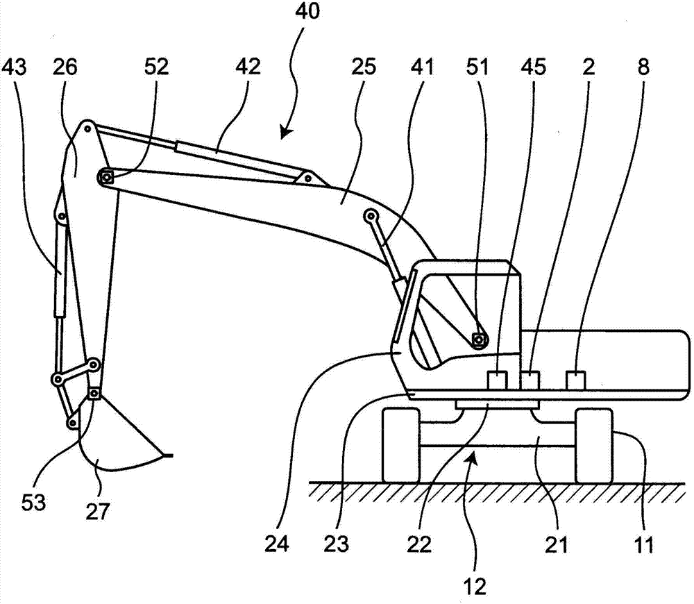
[0082] like figure 1 As shown, a hydraulic excavator as an example of the construction machine of the first embodiment includes a traveling device 11 and a body 12 provided on the traveling device 11 , and the body 12 has a lower portion 21 supported by the traveling device 11 ; An upper turntable 23 is provided on the lower part 21 so as to be able to turn by means of a turn mechanism 22 . A cab 24 is provided on one side in front of the turntable 23 , and a boom 25 is provided at the front center of the turntable 23 so as to be able to pitch. An arm 26 is provided at the front end of the boom 25 so as to be rotatable up and down, and a bucket 27 is provided at the front end of the arm 26 so as to be rotatable.

[0083] The boom 25 is pitched by the boom hydraulic cylinder 41 , the arm 26 is rotated by the arm hydraulic cylinder 42 , and the bucket 27 is rotated by the bucket hydraulic cylinder 43 . The hydraulic cylinders 41, 42, 43 described above are examples of actuator...

no. 2 approach

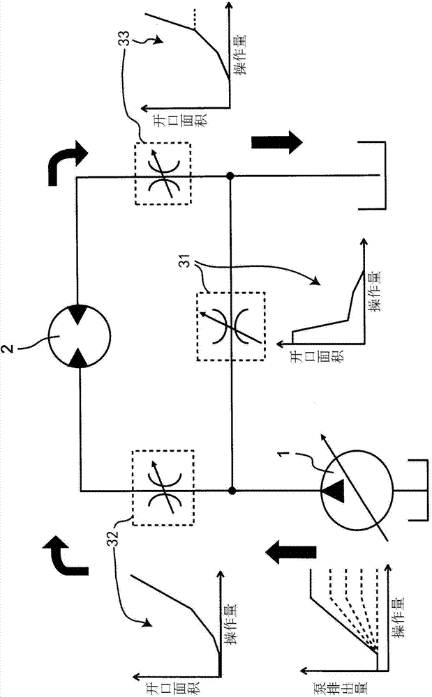
[0105] A hydraulic excavator as an example of the construction machine of the second embodiment, according to figure 1 The output of the boom rotation angle sensor 51 is shown to Figure 5 The illustrated pattern of the discharge amount of the hydraulic pump 1 at the time of correction is different from the hydraulic excavator of the first embodiment only in that the pattern is further corrected.

[0106] Therefore, since the hardware of the second embodiment is the same as that of the first embodiment, citing Figure 1~3 , Figure 5 And its description, only the different structures will be described below.

[0107] The second embodiment of Figure 8 The flow chart shown is the same as that of the first embodiment Figure 4 The flow chart shown is only the same as that in which step S6 has been added. Figure 4 Because they are different, steps S1 to S5 are omitted by citing the description of the first embodiment, and only step S6 will be described below.

[0108] The co...


PUM


Abstract

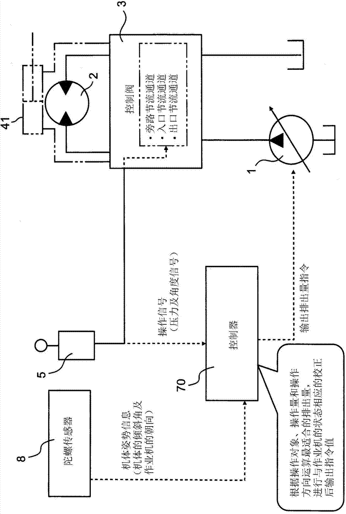
The present invention provides a construction machine, which can inhibit the falling down of the machine body and can reduce the fatigue of an operator by using a simple and chip structure. A controller performs corrective control corresponding to the attitude of a machine body (12) according to the output of a gyro sensor (8) to reduce the output of a hydraulic pump (1), so that the machine body (12) is not prone to fall down. Therefore, the action of a hydraulic cylinder (41) that drives a boom (25) becomes slower than usual, and the operation of the operator is facilitated, so that the falling down of the machine body is inhibited, and the fatigue of the operator is reduced.

Description

technical field [0001] The present invention relates to construction machines such as hydraulic excavators, cranes and the like. Background technique [0002] Conventionally, as a construction machine, there is a construction machine described in JP-A-7-180192 (Patent Document 1). [0003] This conventional construction machine calculates the static toppling moment and the dynamic toppling moment by the calculation unit based on the outputs of the inclination angle sensor of the machine body, the rotation angle sensor of the revolving body, the boom rotation angle sensor, and the arm rotation angle sensor, and obtains the static toppling moment. The sum of the dumping torque and the dynamic dumping torque, if the dumping condition is satisfied, the proportional solenoid valve is controlled to reduce the oil supplied to the hydraulic motor driving the rotary body, decelerate the rotary body, and prevent the dumping. [0004] prior art literature [0005] patent documents ...

Claims


Application Information

Patent Timeline
IPC IPC(8): E02F9/22B66C13/20B66C13/16B66C23/86
Inventor 濑川均
Owner DAIKIN IND LTD
Learn More