Packer

A technology of packer and center pipe, which is applied in the field of packers, can solve problems such as the difficulty of sealing the rubber sleeve, irregular well walls, and rupture of the rubber sleeve, and achieve good sealing effect, convenient operation, and wide application range Effect

Inactive Publication Date: 2015-04-15
扬州市油田金达实业有限公司
View PDF0 Cites 1 Cited by
  • Summary
  • Abstract
  • Description
  • Claims
  • Application Information

AI Technical Summary

Problems solved by technology

However, after the rubber barrel of this tool has been lowered for thousands of meters or even thousands of meters after entering the well, it will be damaged in advance by friction and scraping with the well wall. When the liquid enters the rubber barrel and reaches a certain pressure, it is easy to There is a phenomenon of rubber tube rupture; in addition, the well wall of the rubber tube part is irregular, and it is difficult to achieve a good seal when the rubber tube expands

Method used


Image

  • Packer

Examples


Embodiment Construction

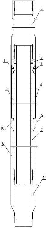
[0012] A packer, comprising a lower joint 1, a central pipe 2 and a lifting joint 3, the lower joint 1 and the lifting joint 3 are respectively sleeved on both ends of the central pipe 2, the lower end of the lifting joint 3 is sleeved with an outer tube 4, the outer tube 4 and the central tube 2 are provided with a piston sleeve 5, the upper end of the piston sleeve 5 is fixedly connected with the outer wall of the central tube 2 through a shear pin 6, and a number of liquid inlet holes 7 are arranged on the side wall of the central tube 2 and are located between the piston sleeve 5 and the outer wall of the central tube 2. Between the lifting joint 3, between the lower joint 1 and the piston sleeve 5, there are sequentially provided a rubber cylinder 8, a slope nipple 9 and a stop ring 10 from bottom to top, and the lower end of the slope nipple 9 is wedged into the inner side of the upper end of the rubber cylinder 8, The anti-retraction ring 10 is wedged into the inner side...


PUM


Abstract

The invention relates to a packer. The packer comprises a lower joint, a central pipe and a lifting joint, wherein the lower joint and the lifting joint are arranged at both ends of the central pipe in a sleeve mode; the lower outer circumference of the lifting joint is provided with an external pipe in a sleeve mode; a piston casing pipe is arranged between the external pipe and the central pipe, the upper end of the piston casing pipe is fixedly connected with the outer wall of the central pipe through a shear pin; the side wall of the central pipe is provided with a plurality of inlet holes between the piston casing pipe and the lifting joint; a rubber barrel, a slope short joint and a retaining ring are sequentially arranged between the lower joint and the piston casing pipe from top to bottom, the lower end of the slop short joint is welded inside the upper end of the rubber barrel, and the retaining ring is wedged inside the upper end of the slope short joint; the outer surface of the central pipe is provided with hangnails for snapping the retaining ring and preventing the slope short joint from moving upwards. The packer is simple in structure, convenient, safe and reliable to operate, high in packing effects without changing original well cementing operation processes, and wide in application range. The packer can be applied to oil-gas wells in different conditions as well as can be matched with other well cementing tools to achieve multi-tool construction of the same well.

Description

technical field [0001] The invention relates to a packer and belongs to the technical field of downhole tools for oil and gas well cementing. Background technique [0002] Oilfield cementing operations encounter more complex oil and gas wells, and the methods of sealing and bridging the annular space outside the casing are adopted for various purposes, so as to improve and enhance the cementing quality of oil and gas wells. This method is usually achieved using packers. Therefore, the packer is an important cementing downhole tool. [0003] The currently used packer uses liquid to enter the rubber tube outside the pipe, forcing the rubber tube to expand, thereby blocking the annular space between the outer wall of the casing and the well wall, and achieving the isolation and bridging of the annular space outside the casing. Purpose. However, after the rubber barrel of this tool has been lowered for thousands of meters or even thousands of meters after entering the well, i...

Claims


Application Information

Patent Timeline
Patent Type & Authority Applications(China)
IPC IPC(8): E21B33/127
CPCE21B33/1208
Inventor 顾业成仲冠宇
Owner 扬州市油田金达实业有限公司
Why Eureka
Try Eureka