hydraulic cylinder

A technology for hydraulic cylinders and cylinder barrels, which is applied in the field of hydraulic cylinders, and can solve the problems of not being able to meet the restrictions on the dimensions of multi-stage hydraulic cylinders, being unable to meet the restrictions on the dimensions of multi-stage hydraulic cylinders, and being too large

Active Publication Date: 2016-06-01
HUNAN TELI HYDRAULIC +1
View PDF8 Cites 0 Cited by
  • Summary
  • Abstract
  • Description
  • Claims
  • Application Information

AI Technical Summary

Problems solved by technology

Taking multi-stage hydraulic cylinders as an example, the current design of multi-stage hydraulic cylinders is limited by the external dimensions, and the difference between the cylinder diameter and the secondary rod diameter is small. figure 1 It shows a multi-stage hydraulic cylinder in the prior art, the cylinder bottom 2 and the cylinder barrel 1 are connected by welding, and a seal is provided between the secondary cylinder rod 4 and the cylinder rod extension end of the cylinder barrel 1 The guide sleeve 3 is sealed. The existence of the guide sleeve 3 makes the wall thickness of the cylinder rod extension end of the cylinder 1 very thin, which reduces the strength of the hydraulic cylinder.
[0003] figure 2 It shows another multi-stage hydraulic cylinder in the prior art, the cylinder bottom 2 and the cylinder barrel 1 are also connected by welding, and the second-stage cylinder rod 4 and the cylinder rod extension end of the cylinder barrel 1 are also connected by setting The guide sleeve 3 with seals is sealed. In order to ensure the strength of the hydraulic cylinder, the outer diameter of the end of the cylinder 1 where the cylinder rod protrudes is increased, so that it cannot meet the external dimension restrictions of the multi-stage hydraulic cylinder.
[0004] image 3 In another multi-stage hydraulic cylinder in the prior art, a seal is provided on the inner peripheral surface of the cylinder rod extension end of the cylinder barrel 1, so there is no need to pass through figure 1 and figure 2 The guide sleeve 3 in the middle is used to seal the secondary cylinder rod 4, so the size of the cylinder rod extension end of the cylinder 1 can meet the size limit requirements, but in this case, due to the constraints of the size of the cylinder 1 itself (that is, the cylinder 1 The inner diameter of the cylinder rod extension end of the cylinder barrel 1 is relatively small, which is smaller than the inner diameter of the end of the cylinder 1 connected to the cylinder bottom 2), and the secondary cylinder rod 4 cannot usually be disassembled through the cylinder rod extension end of the cylinder barrel 1 (inserted or pull out), so at this time the cylinder bottom 2 and the cylinder barrel 1 are detachably connected through a flange structure so that the secondary cylinder rod 4 can be disassembled through the end of the cylinder barrel 1 connected to the cylinder bottom 2 ( Insert or pull out), the flange structure makes the size of the end of the cylinder 1 connected to the cylinder bottom 2 too large, and cannot meet the external dimension limit of the multi-stage hydraulic cylinder

Method used


Image

  • hydraulic cylinder
  • hydraulic cylinder
  • hydraulic cylinder

Examples


Embodiment Construction

[0034] Specific embodiments of the present invention will be described in detail below in conjunction with the accompanying drawings. It should be understood that the specific embodiments described here are only used to illustrate and explain the present invention, and are not intended to limit the present invention.

[0035] In the present invention, in the case of no contrary description, the used orientation words such as "up, down, left and right" usually refer to the up, down, left and right shown in the accompanying drawings; "inside and outside" Refers to the inside and outside of the outline of each part itself.

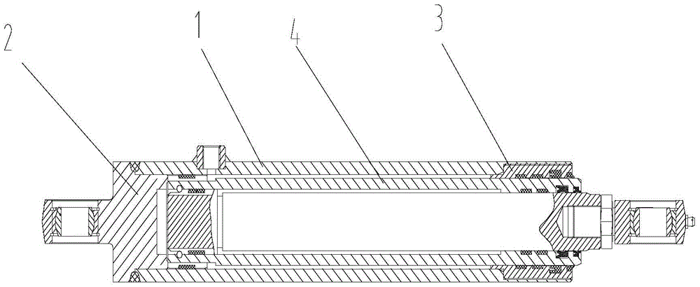
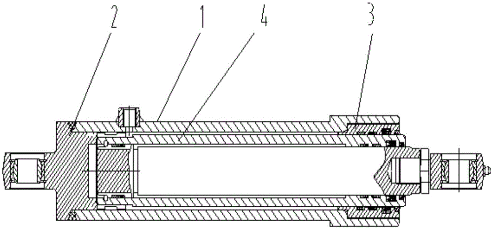
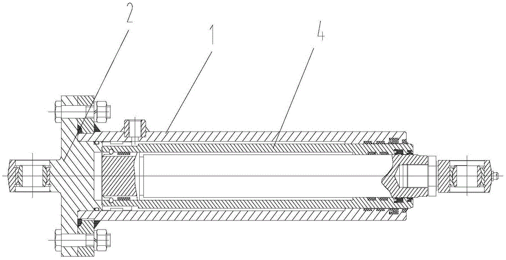
[0036] see Figure 4 , the present invention provides a hydraulic cylinder, the hydraulic cylinder includes a cylinder 1, one end of the cylinder 1 is connected with a cylinder bottom 2, and the other end is formed as a cylinder rod extension end, wherein the inner peripheral surface of the cylinder rod extension end A first sealing member 5 (such as a rubb...


PUM


Abstract

The invention discloses a hydraulic cylinder, including a cylinder barrel (1), wherein one end of the cylinder barrel (1) is connected with a cylinder bottom (2) while the other end forms a cylinder rod extending end, a first sealing member (5) is arranged on the inner peripheral surface of the cylinder rod extending end, the cylinder barrel (1) and the cylinder bottom (2) are fixed with each other by a positioning member positioned in the cylinder barrel (1) and simultaneously stopping the cylinder barrel (1) and the cylinder bottom (2). The hydraulic cylinder can simultaneously meet the requirements on strength, assembly and dimensional limit.

Description

technical field [0001] The invention relates to the field of hydraulic components, in particular to a hydraulic cylinder. Background technique [0002] Hydraulic cylinders have many requirements in terms of their assembly, size and strength. Taking multi-stage hydraulic cylinders as an example, the current design of multi-stage hydraulic cylinders is limited by the external dimensions, and the difference between the cylinder diameter and the secondary rod diameter is small. figure 1 It shows a multi-stage hydraulic cylinder in the prior art, the cylinder bottom 2 and the cylinder barrel 1 are connected by welding, and a seal is provided between the secondary cylinder rod 4 and the cylinder rod extension end of the cylinder barrel 1 The guide sleeve 3 is sealed, and the existence of the guide sleeve 3 makes the wall thickness of the cylinder rod extension end of the cylinder barrel 1 very thin, which reduces the strength of the hydraulic cylinder. [0003] figure 2 It sho...

Claims


Application Information

Patent Timeline
Patent Type & Authority Patents(China)
IPC IPC(8): F15B15/14F15B15/20
CPCF15B15/1428F15B15/1461
Inventor 谢涛谢志勇左美燕
Owner HUNAN TELI HYDRAULIC
Why Eureka
Try Eureka