Domestic water heater water-saving device

A technology for water-saving devices and water heaters, applied in valve devices, fluid heaters, valve operation/release devices, etc., can solve the problems of wasteful use of water resources, inconvenience, etc., and achieve increased sensitivity, reduced processing accuracy, and simple structure reasonable effect

Active Publication Date: 2015-04-15
梁晓军
View PDF7 Cites 0 Cited by
  • Summary
  • Abstract
  • Description
  • Claims
  • Application Information

AI Technical Summary

Problems solved by technology

[0002] At present, there is a certain distance between the water outlet and the nozzle of the water heater in use, especially for domestic gas water heaters, the pipes used are often longer for safety reasons, so it is necessary to drain the cold water in the pipes during use. Wait until the hot water can be used, which causes a lot of waste of water resources and inconvenience in use. The technical solution in the patent application number ZL201410591843.3 is "a water-saving device for water heaters". The water outlet end of the regulating valve is provided with a water storage barrel and a self-priming tee. The outer sleeve is provided with a water outlet on the side of the upper end of the inner sleeve, the outer sleeve is sleeved on the inner sleeve, the floating ball is sleeved on the outer sleeve, the sliding valve core and the inner and outer sleeves are combined to form a float valve, and the sliding valve core is set on the Between the inner and outer sleeves, the sliding valve core is slidingly matched with the inner sleeve. The side of the sliding valve core is provided with a water outlet window and a water outlet through hole. The upper end of the sliding valve core is provided with a water outlet baffle. There is a gap between them, and a sliding sleeve is provided on the outer casing, which is connected to the sliding valve core through the chute hole on the outer casing; there is a quick-opening water channel on the self-priming tee, and one end of it is connected to the self-priming The other end of the water channel is connected to the water channel set between the inner and outer casings, and the other end of the water channel is connected to the lower end of the sliding valve core. The qui

Method used


Image

  • Domestic water heater water-saving device
  • Domestic water heater water-saving device
  • Domestic water heater water-saving device

Examples


Example Embodiment

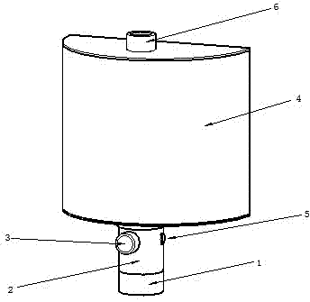
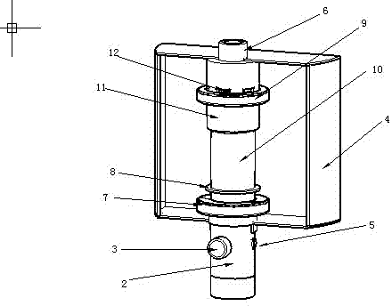
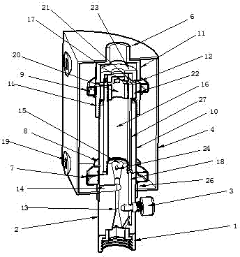
[0028] The water-saving device for a household water heater in the embodiment mainly includes a water inlet joint (1), a button type quick opening valve (3), a self-priming tee (2), an outer casing (10), an inner casing (16), The lower floating ball (7), the upper floating ball (9), the water storage barrel (4), the water volume adjustment bolt (5), the floating ball valve (11), the sliding valve core (22), and the water outlet (6) are composed of water storage The bucket (4) is semi-cylindrical, the water inlet of the self-priming tee (2) is connected to the water outlet of the hot and cold water regulating valve through the water inlet joint (1), and the outlet of the upper end of the float valve (11) The water outlet (6) connects the water pipe to the nozzle, the self-priming tee (2) is arranged on the bung mouth of the water storage bucket (4), and the button type quick opening valve (3) and the water adjustment bolt (5) are arranged on the water storage bucket ( 4) Outsid...


PUM


Abstract

The invention discloses a domestic water heater water-saving device which comprises a water storage tank, a self-suction tee, an inner casing pipe, an outer casing pipe and a sliding valve element, wherein the self-suction tee is connected with the water outlet end of a cold-hot water regulation valve; a water suction hole of the self-suction tee is formed in the water storage tank; a water outlet of the self-suction tee is connected with the water inlet end of a ball float valve through the inner casing pipe and the outer casing pipe. The domestic water heater water-saving device is characterized in that the ball float valve, an upper floating ball and a lower floating ball are arranged in the water storage tank; the upper floating ball sleeves the surface of the ball float valve; a sealing casing pipe is arranged on the lower floating ball and sleeves the lower end part of the outer casing pipe; after the stored water is pumped out, the sealing casing pipe falls to close the water suction hole of the self-suction tee; a water storage hole is formed in the side surface of the ball float valve; the stored water enters in the water storage tank through the water storage hole; when water storage tank is fully filled with water, the upper floating ball floats upwards to close the water storage hole and the sliding valve element opens the water outlet under the action of water pressure; a compensation water channel is formed between the water inlet and the water outlet of the self-suction tee. By adopting the technical scheme, the water in the water storage tank is uniformly pumped to supply to the sprayer by the self-suction tee in the water-out process through the action of the upper floating ball, the lower floating ball and the compensation water channel.

Description

technical field [0001] The invention relates to a water heater, in particular to a water-saving device for a domestic water heater. technical background [0002] At present, there is a certain distance between the water outlet and the nozzle of the water heater in use, especially for domestic gas water heaters, the pipes used are often longer for safety reasons, so it is necessary to drain the cold water in the pipes during use. Wait until the hot water can be used, which causes a lot of waste of water resources and inconvenience in use. The technical solution in the patent application number ZL201410591843.3 is "a water-saving device for water heaters". The water outlet end of the regulating valve is provided with a water storage barrel and a self-priming tee. The outer sleeve is provided with a water outlet on the side of the upper end of the inner sleeve, the outer sleeve is sleeved on the inner sleeve, the floating ball is sleeved on the outer sleeve, the sliding valve ...

Claims


Application Information

Patent Timeline
IPC IPC(8): F24H9/00F16K31/30
Inventor 梁晓军
Owner 梁晓军
Why Eureka
Try Eureka