
Cascade thrust reverser for an aircraft turbofan

A thrust reverser and blade cascade technology, which can be used in machine/engine, jet propulsion, etc., to solve problems such as aerodynamic flow quality and hinge wear that affect cold air flow

Active Publication Date: 2015-04-15
AIRCELLE
View PDF7 Cites 0 Cited by
  • Summary
  • Abstract
  • Description
  • Claims
  • Application Information

AI Technical Summary

Problems solved by technology

[0007] A known recurring problem is the vibration of the thrust reverser flaps in the case of direct injection, affecting the aerodynamic flow quality of the cold air stream and causing different hinges involved in moving these thrust reverser flaps premature wear of

Method used


Image

  • Cascade thrust reverser for an aircraft turbofan
  • Cascade thrust reverser for an aircraft turbofan
  • Cascade thrust reverser for an aircraft turbofan

Examples


Embodiment Construction

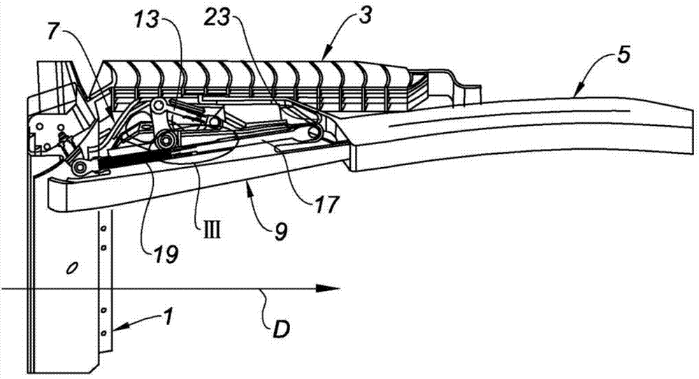
[0036] like figure 1 As shown, the thrust reverser of the present invention comprises a fixed front frame 1 integral with the fan housing of the turbojet engine (not shown).

[0037] A fixed front frame 1 defining a substantially annular shape supports a plurality of deflecting cascades 3 arranged side by side at the edges of the front frame.

[0038] Its upstream portion of the sliding cover 5 includes a housing 7 movable between a direct spray position and an indirect spray position, as in figure 1 The casing 7 covers the deflection cascade 3 in the direct injection position shown, while the Figure 9 In the position of the indirect injection shown in , the casing 7 exposes the deflection vanes 3 .

[0039] Inside the shell 7 of the sliding cowl 5 are mounted side by side a plurality of thrust reverser baffles 9 which are pivotally mounted on such as figure 1 direct injection position shown and as Figure 9 Between the reverse injection positions shown, in which the thru...


PUM


Abstract

The invention relates to a cascade thrust reverser configured such that, when a sliding cowl (5) and a flap (9) are in a direct jet position, a hook (25) is held in engagement with a hook (23) and the flap (9) is immobilized at the bottom of a recess (7) by said rod (17) of a telescopic connecting rod (11) subjected to pre-stress generated by a compressed spring located in the body (15) of said connecting rod, and when the sliding cowl (5) starts to slide from the direct jet position thereof toward the reverse jet position thereof, the hook (25) releases from the hook (23) and the rod (17) engages with an extension in the body (15), thereby enabling the flap (9) to be rotated from the direct jet position thereof toward the reverse jet position thereof due to the tensile force exerted by said rod (17).

Description

technical field [0001] The invention relates to a cascade thrust reverser for an aircraft turbojet engine. Background technique [0002] As is known, a cascade thrust reverser generally comprises a plurality of deflected cascades arranged downstream of the turbojet fan, and a cowl delimiting the flow of cold air for the turbojet, said cowl being slidably mounted on a so-called "direct injection " between the position called "reverse injection", in which the shroud covers the deflector vanes, and in the reverse injection position the shroud leaves these deflector vanes exposed. [0003] The position of the direct injection corresponds to the working mode of the turbojet engine and its associated nacelle in the cruise situation. [0004] The mode of operation of the reverse injection corresponds to a landing situation in which a part of the flow of cold air generated by the fan is directed towards the front of the nacelle, in a manner that can assist the braking of the aircra...

Claims


Application Information

Patent Timeline
IPC IPC(8): F02K1/62F02K1/72F02K1/76
CPCF02K1/72F02K1/625F02K1/766F02K1/763
Inventor 文森特·佩隆洛朗·乔治·瓦勒鲁瓦弗兰克·德普欧特尔
Owner AIRCELLE
Features
  • Generate Ideas
  • Intellectual Property
  • Life Sciences
  • Materials
  • Tech Scout
  • Unparalleled Data Quality
  • Higher Quality Content
  • 60% Fewer Hallucinations
Learn More