Integrated phase connection isolator with individual phase isolator

A technology of isolators and phase separators, applied in the manufacture of stator/rotor body, magnetic circuit shape/style/structure, electric components, etc., can solve problems such as reducing space

Inactive Publication Date: 2015-04-15
REMY TECHNOLOGIES LLC
View PDF5 Cites 3 Cited by
  • Summary
  • Abstract
  • Description
  • Claims
  • Application Information

AI Technical Summary

Problems solved by technology

Furthermore, when bus bar assemblies for multiple phases are at the axial ends of the stator, separate annular isolators may be required to isolate the bus bars from the individual coils, and such annular isolators typically require alignment and reduce the Perform conductor soldering and connection to available space

Method used


Image

  • Integrated phase connection isolator with individual phase isolator
  • Integrated phase connection isolator with individual phase isolator
  • Integrated phase connection isolator with individual phase isolator

Examples


Embodiment Construction

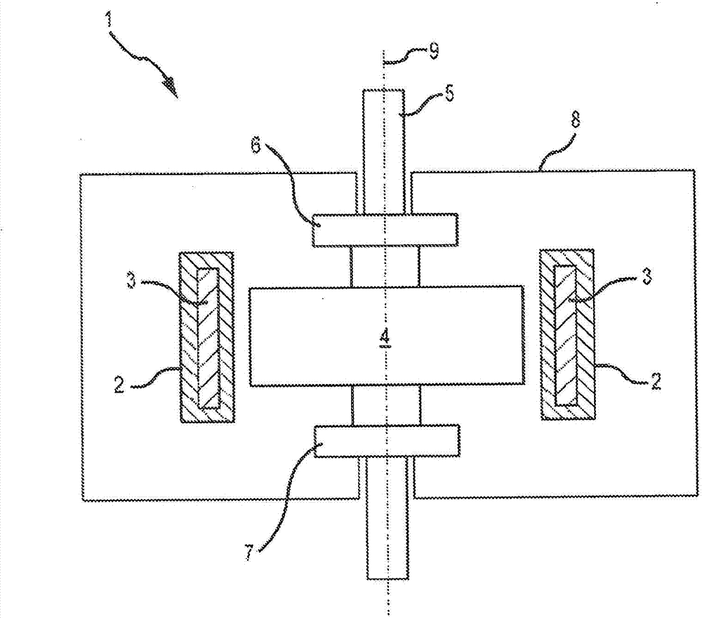
[0029] figure 1 Is a schematic illustration of an exemplary electric machine 1 having a stator 2 comprising a stator winding 3, eg one or more coils. The annular rotor body 4 may also comprise windings and / or permanent magnets and / or conductor bars formed eg by a molding process. The rotor body 4 is part of a rotor comprising an output shaft 5 supported by a front bearing assembly 6 and a rear bearing assembly 7 . The bearing assemblies 6 , 7 are fixed to the housing 8 . In general, the stator 2 and rotor body 4 are substantially cylindrical in shape and concentric with a central longitudinal axis 9 . Although the rotor body 4 is shown as being radially inside the stator 2 , alternatively, the rotor body 4 may be formed radially outside the stator 2 in various embodiments. The electric machine 1 may be a motor / generator or other device. In an exemplary embodiment, the electric machine 1 may be a traction motor for a hybrid vehicle or an electric vehicle. The housing 8 may...


PUM

PropertyMeasurementUnit
thicknessaaaaaaaaaa

Abstract

A stator assembly includes a coil isolator having a first flange, a phase separator, and a living hinge connecting the first flange and the phase separator, the coil isolator structured for enclosing a stator lamination stack and for winding a coil thereon in electrical isolation from the stack, the phase separator being radially closeable for enclosing a portion of the coil within the coil isolator. A method of forming a stator includes placing an isolator onto a lamination stack segment, winding a coil onto the isolator, folding a phase separator of the isolator to enclose a portion of the coil, and placing a plurality of bus bars onto the phase separator in physical partition from one another. A method of insulating a phase bus from a stator coil includes forming a coil insulator having a bobbin, a phase separator, and a living hinge coupling the bobbin to the phase separator.

Description

[0001] Related Patent Applications [0002] This application claims priority to US Patent Application Serial No. 61 / 670,485, filed July 11, 2012, which is hereby incorporated by reference in its entirety. technical field [0003] The present invention relates to electric machines, and more particularly, the present invention relates to electric machines with segmented stators. Background technique [0004] Higher efficiencies and increased power and torque densities are increasingly being demanded in electrical machines. Conventional electric machines typically have a stator core formed from stacked laminations having inwardly projecting teeth with slots defined between adjacent teeth. In many electric machines, such as brushless AC and DC motors, the coils are wound around a single tooth so that the copper wire forming the coils fills the slots. When the stator core is a single structure forming a complete ring, manufacturing difficulties arise in accessing the slots, whi...

Claims


Application Information

Patent Timeline
Patent Type & Authority Applications(China)
IPC IPC(8): H02K1/18H02K3/46
CPCY10T29/49009H02K15/02H02K2203/09H02K1/148H02K3/46H02K3/345H02K3/522H02K2203/12
Inventor K·H·万B·D·钱伯林
Owner REMY TECHNOLOGIES LLC
Why Eureka
Try Eureka