
Integrated pump valve module

An integrated, pump-valve technology, used in cardiac catheterization, massage aids, physical therapy, etc., can solve the problems of difficult to guarantee the accuracy of measurement data, difficult to guarantee sealing and reliability, unstable cuff airflow, etc. Low cost, meet the requirements of sealing, excellent rigidity and wear resistance

Active Publication Date: 2016-08-24
ANDON HEALTH CO LTD +1
View PDF8 Cites 0 Cited by
  • Summary
  • Abstract
  • Description
  • Claims
  • Application Information

AI Technical Summary

Problems solved by technology

Although the integrated air pump can solve the technical problem of complex structure and large volume of components composed of the pressure air pump and the quick release valve in the prior art, it lacks the slow release valve, so it is only suitable for the upper air measurement method; the measurement process requires The integrated air pump is always pressurized, which causes the air flow in the cuff to be unstable during the measurement process, making it difficult to guarantee the accuracy of the measurement data; the frequent deformation of the elastic body in the air release valve can easily lead to its hardening and shorten its life, and there is a seal Difficult to guarantee sex and reliability

Method used


Image

  • Integrated pump valve module
  • Integrated pump valve module
  • Integrated pump valve module

Examples


Embodiment 1

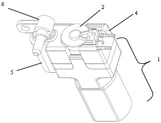
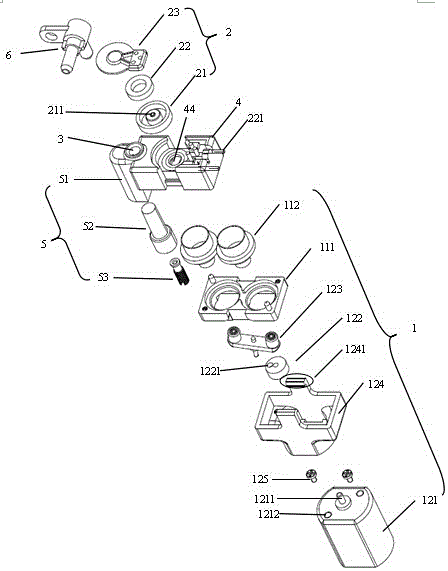
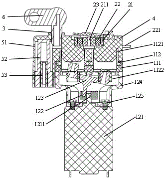
[0024] Such as figure 1 , figure 2 with image 3 As shown, the integrated pump valve of the present invention includes a booster pump 1 , an air release valve 2 , an air outlet 3 and an upper cover 4 , wherein the air outlet 3 and the air release valve 2 are both arranged on the upper cover 4 . The deflation valve 2 is a solenoid valve. The bottom of the upper cover 4 includes two annular grooves 41, 42, and the annular grooves 41, 42 open downward. Two pistons 112 corresponding to the annular grooves 41 , 42 are provided in the booster pump 1 . The inner surfaces of the two annular grooves 41, 42 are in close contact with the upper ends 1121 of the two pistons, and the opposite side 43 of the two annular grooves 41, 42 is directly connected to the opening 44 at the top of the upper cover at the bottom of the grooves. The opening 44 is located below the deflation valve 2, and the bottom end of one annular groove 41 on the side 45 away from the other annular grooves 42 dir...

Embodiment 2

[0033] On the basis of Embodiment 1, a slow air release valve 5 is also provided on the side of the upper cover 4 close to the air outlet 3 , and the air flow channel of the slow air release valve 5 communicates with the air flow channel of the upper cover 4 . The slow release valve 5 can be a normally open small hole arranged on the upper cover 4; the following structure can also be adopted: the slow release valve 5 is composed of a core seat 51, a rubber core 52 and a copper core 53, and the core seat 51 There is an air core chamber for the passage of gas, the air core chamber communicates with the air flow channel in the upper cover, the rubber core 52 is placed in the air core chamber, one end of the rubber core 52 is closed and the other end is open, the rubber core 52 The open end of the core seat 51 is interference fit with the end of the core seat 51. There is a cutout 54 on the side wall of the rubber core 51. The length of the cutout 54 in the radial direction of the ...


PUM


Abstract

The invention discloses an integrated pump valve module. The integrated pump valve module comprises a booster pump, an air vent valve, an air outlet and an upper cover. The air outlet and the air vent valve are arranged on the upper cover. An airflow channel is formed in the upper cover and communicated with the booster pump, the air vent valve and the air outlet. The air vent valve is a solenoid valve. The bottom of the upper cover is provided with a plurality of annular grooves. The annular grooves are open downwards. The inner side faces of the annular grooves are in close fit with the upper ends of pistons in the booster pump. The opposite sides of the annular grooves are directly communicated with an opening in the top end of the upper cover at the bottom ends of the grooves. The opening is located below the air vent valve. The bottom end of the side, away from the other annular grooves, of one annular groove is directly communicated with the air outlet, so that the airflow channel is formed in the upper cover. The integrated pump valve module has the advantages that the structure is intensive, the size is small, parts are reasonable in design, the manufacturing cost is low, and can be applied to the fields such as sphygmomanometers and massage devices.

Description

technical field [0001] The invention relates to a pump valve used in a sphygmomanometer, a massage instrument, etc., and in particular to a compact and component-intensive integrated pump valve module. Background technique [0002] One of the important parts of electronic sphygmomanometers currently on the market is an assembly composed of a pressure air pump, a quick release valve, and a slow release valve. They need to be connected by complicated rubber hoses, three-way or four-way joints , larger in size. When assembling the above components, the hose needs to be bent to a specified angle. If the assembly operator is not careful and the bend is too large, it will cause the hose to be closed and affect the performance of the electronic sphygmomanometer, and it will cost more to assemble the above components. Many working hours and high labor intensity. [0003] Chinese patent document CN103767695A (publication date: 2014.05.07) discloses an integrated air pump. A purely ...

Claims


Application Information

Patent Timeline
Patent Type & Authority Patents(China)
IPC IPC(8): A61B5/0235A61H23/04
Inventor 叶芳铖王学明何广斌
Owner ANDON HEALTH CO LTD
Learn More