Method and device capable of stably guiding welding wire out

A welding wire and stable technology, applied in welding equipment, arc welding equipment, manufacturing tools, etc., can solve the problems of wire guide wheel and welding wire wear, large welding gun weight and volume, wire skipping, etc., to achieve stable wire feeding speed, welding Good road effect and uniform wire feeding effect

Active Publication Date: 2015-04-22
广西梧州市赢鑫船舶制造有限公司
View PDF5 Cites 1 Cited by
  • Summary
  • Abstract
  • Description
  • Claims
  • Application Information

AI Technical Summary

Problems solved by technology

The wire feeding speed of the wire feeding device of this kind of welding torch is not uniform, so the phenomenon of wire jumping is prone to occur during welding, which makes the speed measuring system of the welding machine give wrong instructions, causing the arc length, arc width and molten pool of the welding torch arc to be unstable, resulting in The width and smoothness of the welding path are not ideal
Domestic welding machines often need to adjust the current and voltage during the welding process, which takes a lot of time
[0004] 2. The existing imported welding machine is equipped with a wire drawing device in the welding torch, and the direction of the force is opposite to that of the wire feeding device to adjust the force balance of the wire feeding device and make the wire feeding speed more uniform. The mechanical power of the machine adopts a DC motor, which belongs to asynchronous drawing, and the interval airway switch is sealed with a mechanical film. The weight and volume of the welding torch are relatively large, which is not easy to move and operate.
The non-synchronous wire drawing device causes the welding torch to slip at different rates during the welding process, causing the wire pressing guide wheel and welding wire to seriously wear the welding wire and produce a sense of frustration, which affects the quality of the welding path
Imported welding machines are expensive, which is not conducive to large-scale promotion and use in the market

Method used


Image

  • Method and device capable of stably guiding welding wire out
  • Method and device capable of stably guiding welding wire out
  • Method and device capable of stably guiding welding wire out

Examples


Embodiment

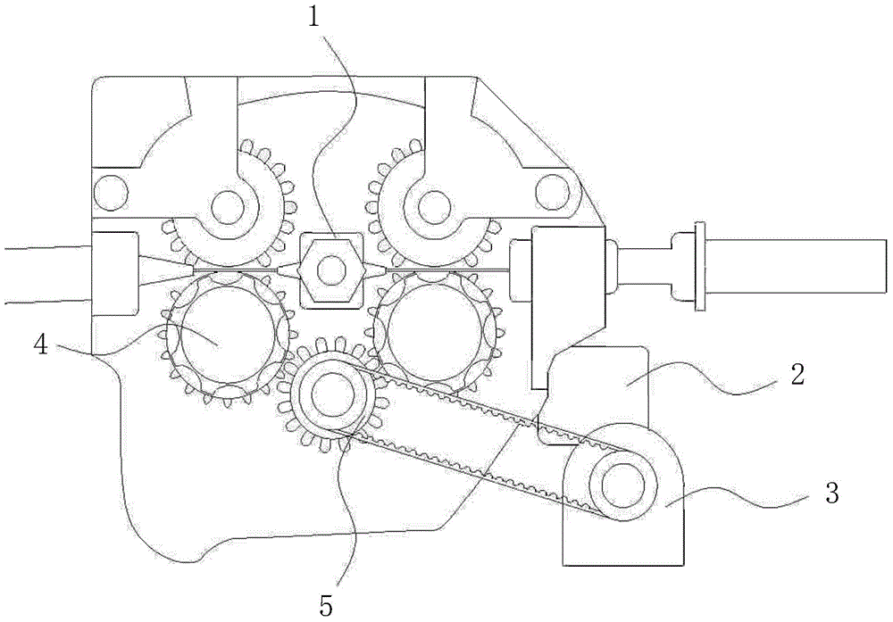
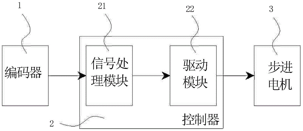
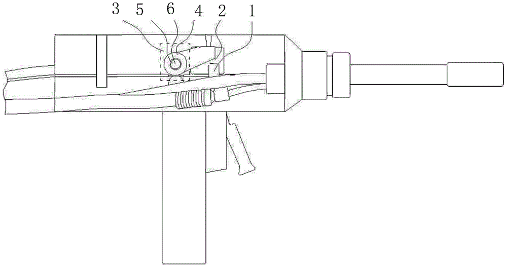
[0033] refer to image 3 As shown, a device that can stably lead out welding wire in this embodiment is arranged on a welding torch, and includes an encoder 1, a controller 2, a stepping motor 3 and a traction wheel set 4, and the encoder 1 is located in the conveying direction of the welding wire. The traction wheel group 4 is made up of a pair of traction wheels, and the traction wheel group 4 is symmetrically arranged on both sides of the welding wire, and the stepper motor 3 is connected with the power of the traction wheel group 4 through the transmission mechanism 5, and the transmission mechanism 5 is a power extension shaft 6, and the stepping motor 3, the power extension shaft 6 drives the traction wheel group 4 to rotate in the opposite direction of welding wire transmission, the signal output end of the encoder 1 is connected to the signal input end of the controller 2, and the signal output end of the controller 2 is connected to the stepping motor 3 signal input t...


PUM


Abstract

The invention discloses a method capable of stably guiding a welding wire out. A traction mechanism synchronous with a welding wire send-out mechanism is additionally arranged on the welding wire send-out mechanism. By the adoption of the method, the wire feeding speed of the welding wire guided out through a welding machine is more stable. The invention further discloses a device capable of stably guiding the welding wire out. The device comprises an encoder, a controller, a stepping motor and traction wheel sets. The encoder is located in the welding wire conveying direction. Each traction wheel set is composed of at least one pair of traction wheels. The traction wheel sets are symmetrically arranged on the two sides of the welding wire. The stepping motor is in power connection with the traction wheel sets through a transmission mechanism. The signal output end of the encoder is connected with the signal input end of the controller. The signal output end of the controller is connected with the signal input end of the stepping motor. The welding machine with the device has the advantages of being even in wire feeding operation, good in welding effect and low in cost.

Description

technical field [0001] The present invention relates to a method for leading out welding wire, more specifically, especially to a method for stably leading out welding wire; the present invention also relates to a device for stably leading out welding wire. Background technique [0002] At present, there are some problems in the welding process of the extreme fusion welding machine on the market, the specific situation is as follows: [0003] 1. Domestic welding machines are generally only equipped with a welding torch of about three meters, and the working range is small. Users need to frequently move the welding machine to change positions during the welding process. The wire feeding speed of the wire feeding device of this kind of welding torch is not uniform, so the phenomenon of wire jumping is prone to occur during welding, which makes the speed measuring system of the welding machine give wrong instructions, causing the arc length, arc width and molten pool of the wel...

Claims


Application Information

Patent Timeline
IPC IPC(8): B23K9/133
CPCB23K9/133
Inventor 麦树雄
Owner 广西梧州市赢鑫船舶制造有限公司
Why Eureka
Try Eureka