
Mechanical and automatic feeding and discharging mechanical device

A technology of mechanical devices and servo motors, which is applied to machine tools, grinders, and metal processing equipment designed for grinding the rotating surface of workpieces. It can solve the problem of difficulty in ensuring the consistency of processed workpieces, the harsh working environment of production personnel, and the difficulty in ensuring product consistency. and other problems, to achieve the effect of convenient wireless remote control operation, saving manpower, and moderate equipment cost

Inactive Publication Date: 2015-04-22
岳睿
View PDF4 Cites 4 Cited by
  • Summary
  • Abstract
  • Description
  • Claims
  • Application Information

AI Technical Summary

Problems solved by technology

Manual loading and unloading, low processing efficiency and fatigue problems
Manual operation, product consistency is difficult to guarantee, manual operation, there will be proficiency, technical level problems, it is difficult to ensure the consistency of processed workpieces
The working environment of the production personnel is harsh, and the operator is always in a noisy and dusty working environment. The working environment will cause harm to the human body, the management cost is high, and the worker's wage cost is high.

Method used


Image

  • Mechanical and automatic feeding and discharging mechanical device

Examples


Embodiment Construction

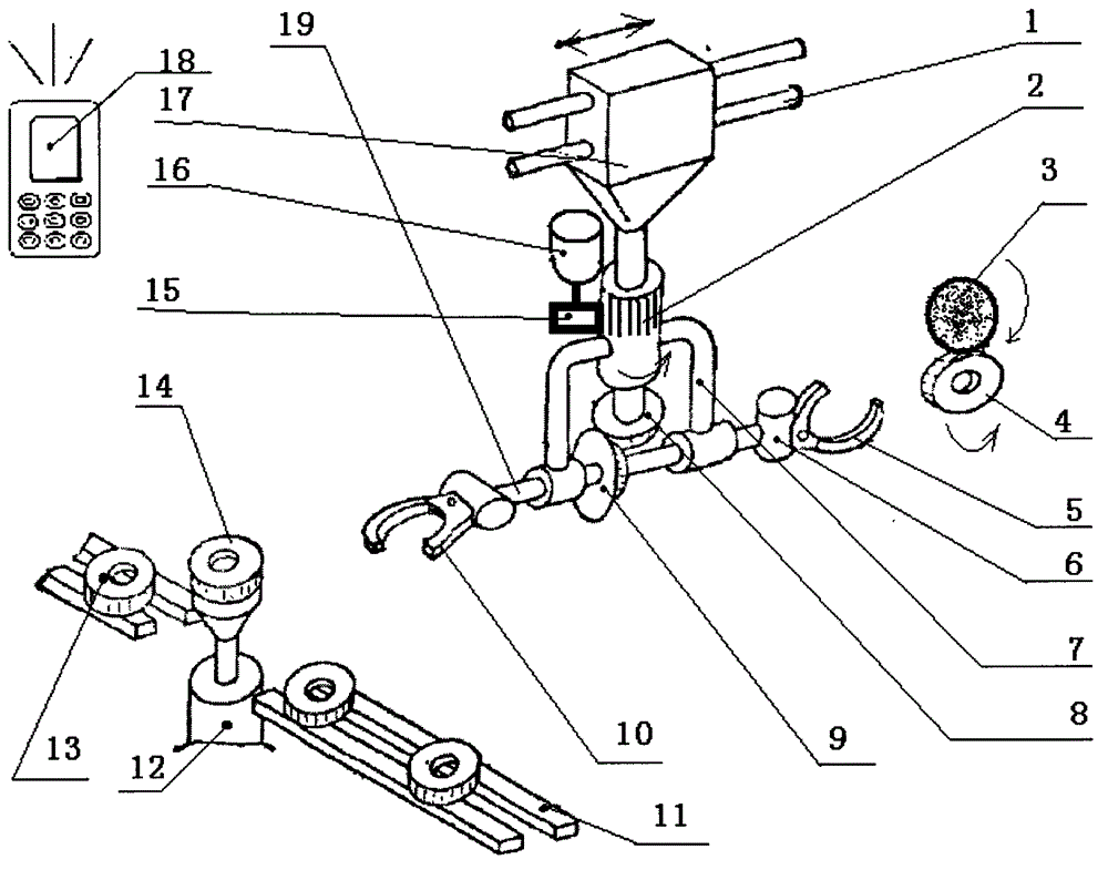
[0023] Such as figure 1 As shown, when the mechanical parts need to grind the outer circle, the parts 14 waiting to be ground can be placed on the conveying line 11, and the transmission device can transfer the parts 14 waiting to be ground to the lifting cylinder 12, and the lifting The oil cylinder 12 has an automatic lifting function. The upper surface of the lifting oil cylinder 12 is provided with a photoelectric sensor. Once the parts 14 waiting for grinding are placed on the upper surface of the lifting oil cylinder 12, the lifting oil cylinder 12 will automatically lift. Once the parts 14 waiting for grinding Taken away by manipulator, lifting oil cylinder 12 descends automatically. Because the moving large slider 17 is controlled by the programmable controller, the moving large sliding block 17 can automatically slide to the left after completing the last working cycle, and at the same time, the servo motor 16 drives the pinion 15 to rotate, and the pinion 15 drives t...


PUM

PropertyMeasurementUnit
Outer diameteraaaaaaaaaa
Modulusaaaaaaaaaa

Abstract

The invention relates to a mechanical and automatic feeding and discharging mechanical device. The mechanical and automatic feeding and discharging mechanical device is composed of arm moving slide bars, a turning gear, long fingers of grasping hands, a horizontal shaft and the like; two arm moving slide bars are horizontally arranged on a wallboard of a machine above a conveying production line, and a movable large slide block has movable fit with the arm moving slide bars; the output shaft of a servo motor is connected with a pinion through a flat key; the pinion is externally engaged to the turning gear, the turning gear has stationary fit with a turning arm, when the turning gear rotates, the turning arm rotates, a fixed gear is arranged on a fixed shaft below the turning gear, and a planetary conical gear is arranged on the horizontal shaft and forms a pair of externally engaged conical gears with the fixed gear. The mechanical and automatic feeding and discharging mechanical device is capable of greatly reducing the workload of operators and saving manpower. The mechanical and automatic feeding and discharging mechanical device realizes mechanical and automatic feeding and discharging. The mechanical and automatic feeding and discharging mechanical device is especially suitable for grinding disc type mechanical parts, realizes to mechanically, automatically and remotely conducting an operation site in a wireless mode, is fast in feeding and discharging speed, and is precise in position.

Description

technical field [0001] The invention relates to a mechanical device for automatic loading and unloading, in particular to a mechanized automatic loading and unloading mechanical device. Background technique [0002] In the current industrial processing enterprises, especially in machinery manufacturing enterprises, the problem of loading and unloading of mechanical parts is often encountered. Manual loading and unloading, the processing efficiency is low, and there will be problems of fatigue. Manual operation, product consistency is difficult to guarantee, manual operation, there will be proficiency, technical level problems, it is difficult to ensure the consistency of processed workpieces. The working environment of the production personnel is harsh, and the operator is always in a noisy and dusty working environment. The working environment will cause harm to the human body, the management cost is high, and the worker's wage cost is high. With the increase of labor cos...

Claims


Application Information

Patent Timeline
IPC IPC(8): B24B5/35
CPCB24B5/355
Inventor 岳睿
Owner 岳睿
Learn More