
An image system laminating machine

A technology of an image system and a laminating machine, which is applied in the directions of lamination device, lamination auxiliary operation, lamination, etc., can solve the problems of waste of human resources, low work efficiency, and no device for detecting unqualified products.

Inactive Publication Date: 2016-08-24
DONGGUAN ZHIAO GENERAL MACHINERY EQUIP
View PDF5 Cites 0 Cited by
  • Summary
  • Abstract
  • Description
  • Claims
  • Application Information

AI Technical Summary

Problems solved by technology

[0003] The technical problem solved by the present invention: the existing backlight film laminating machine has no device for detecting unqualified products. After the product is pasted, it is necessary to manually check whether the product is qualified or manually take it to another detection device to detect whether the product is qualified. Low, waste of human resources, and inaccurate detection

Method used


Image

  • An image system laminating machine
  • An image system laminating machine
  • An image system laminating machine

Examples


Embodiment Construction

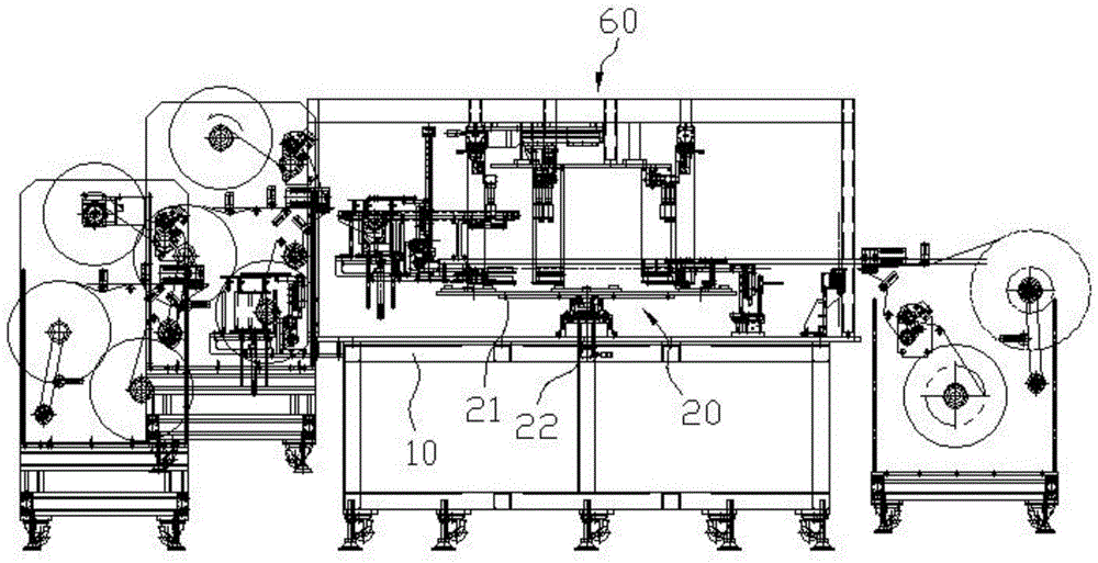
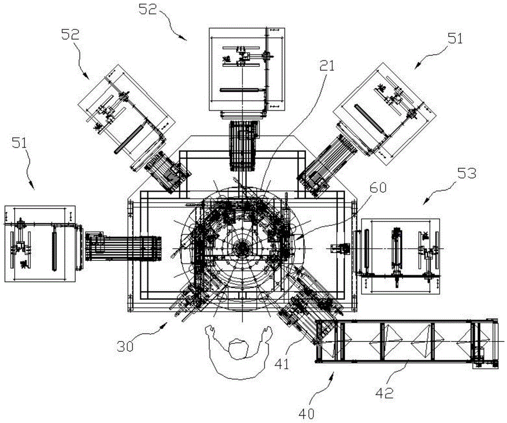
[0041] combine figure 1 , figure 2 , an image system film laminating machine, including a frame 10, a product conveying device 20, a dust removal device 30, a film laminating device, a finished product removal mechanism 40, and an image system 60.

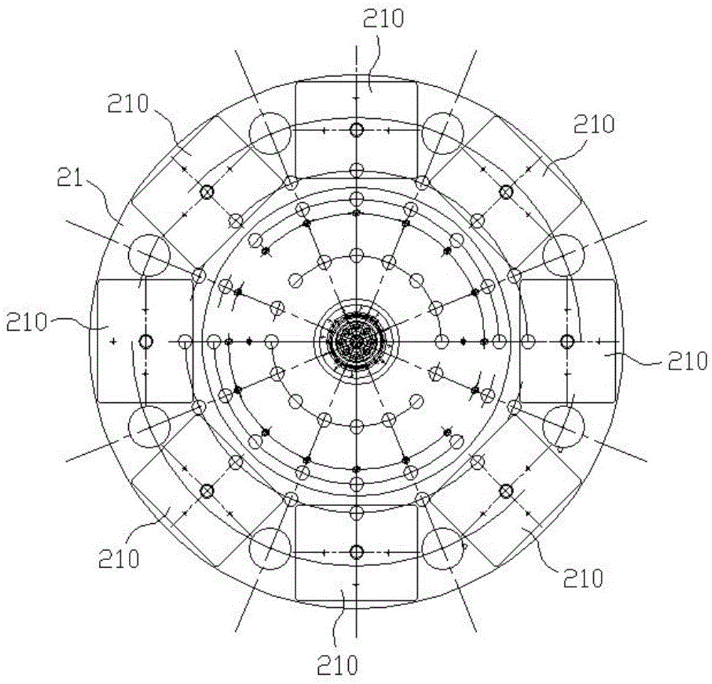
[0042] combine figure 1 , figure 2 , image 3 , the product transfer device 20 includes a turntable 21, a drive shaft 22 installed at the center of the turntable 21, the drive shaft 22 is connected to the motor, the drive shaft 22 is pivotally connected to the frame 10, and the turntable 21 is horizontal It is provided that eight backlight module stations 210 are arranged on the outer ring of the turntable 21 .

[0043] combine Figure 9 , Figure 10 , Figure 11 , the dust removal device 30 includes a bracket 310 , a casing 320 , an air outlet component 330 , a blower, and a cylinder 340 . The housing 320 is fixed on the bracket 310, the bracket 310 is installed on the frame 10, the housing 320 is in the shape of a cuboi...


PUM


Abstract

The invention discloses an image system laminator, comprising a rack, a product conveyer, a dust collector, a laminating device, a product shift-out mechanism and an image system, wherein the product conveyer comprises a turntable; the dust collector, the laminating device and the product shift-out mechanism are sequentially distributed on the periphery of the turntable in the rotation direction of the turntable; a backlight source module is firstly cleaned by the dust collector under the conveying of the turntable and is automatically laminated by various film laminating devices; and the image system captures images of various film laminating states and judges the laminating eligibility of the films in the process of laminating various films and after the laminating is ended, so that the recognition accuracy is improved; improvement of the working efficiency is improved; and finally, the backlight source module is automatically output from the laminator by virtue of the product shift-out mechanism.

Description

technical field [0001] The invention relates to a film laminating machine, in particular to a film laminating machine for a backlight source module with an image system. Background technique [0002] Backlight is a kind of light source located behind the liquid crystal display on the mobile phone, MP4 and GPS, and its luminous effect will directly affect the visual effect of the liquid crystal display module. LCD itself does not emit light, it displays graphics or characters is the result of its light modulation. The current backlight module is mainly used in conjunction with a diffusion film, a light-enhancing film, a light-shielding film, etc. to achieve the purpose of uniformity and concentration of light. At present, films such as diffusion film, light-enhancing film, and light-shielding film are generally pasted on the backlight module by using a film laminating machine. The film laminating machine generally includes a film laminating device, a product conveying device...

Claims


Application Information

Patent Timeline
Patent Type & Authority Patents(China)
IPC IPC(8): B32B37/00
CPCB32B37/10B32B38/162B32B2041/04
Inventor 徐兵
Owner DONGGUAN ZHIAO GENERAL MACHINERY EQUIP
Learn More