Labyrinth type self-locking device of winder

A self-locking device and labyrinth technology, which is applied in the field of labyrinth self-locking devices, can solve problems such as troublesome manufacturing and installation, complex structure, broken teeth, etc.

Active Publication Date: 2015-04-22
SEESA HLDG
View PDF8 Cites 6 Cited by
  • Summary
  • Abstract
  • Description
  • Claims
  • Application Information

AI Technical Summary

Problems solved by technology

The structure of the hose reel mainly includes a shell, a reel is set in the shell, a hose is wound around the reel, and a coil spring is connected to the reel. When the hose is pulled out, the hose will drive the reel to rotate, and the reel will rotate. Drive the coil spring to tighten the pressure storage. When the hose is released, the coil spring will drive the reel to rotate back under the action of the restoring force. The reel drives the hose to retract into the shell. When the hose is pulled out for use, In order to prevent the automatic retraction of the hose, a self-locking mechanism is usually installed in the hose reel, such as the Chinese patent No. On the baffle plate of the inner cavity wall, the baffle plate is provided with a gear block with teeth on one side and a handle that can rotate around the positioning axis, and a spring that makes the dial block rotate and reset. The left half of the baffle plate is fixed with the cover plate, A gear movable groove is formed between the plate and the baffle, and a pinion gear that can mesh with the teeth on the shift block is arranged in the groove. The tooth block is engaged, and the movable tooth block is fixed with the main wheel. The disadvantages of this structure are: complex structure, troublesome manufacture and installation, difficult to control the locking operation of the hose during use, and problems will occur when the hose retracts. Locked, and when suddenly locked, the two gears collide, which is likely to cause broken teeth, poor reliability and other disadvantages

Method used


Image

  • Labyrinth type self-locking device of winder
  • Labyrinth type self-locking device of winder
  • Labyrinth type self-locking device of winder

Examples


Embodiment Construction

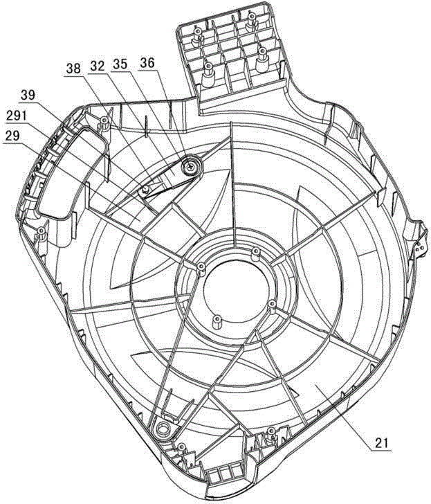
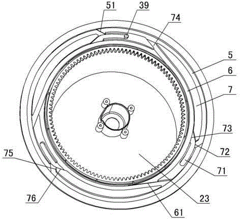
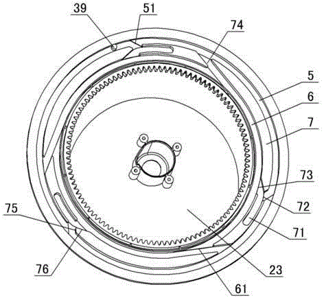
[0014] The invention relates to a labyrinth self-locking device of a hose reel, such as figure 1 — Figure 7As shown, it includes the right cover 21 and the right reel 23 of the hose reel. It is characterized in that: the inner wall of the right cover 21 limits the limiting cavity 29 and the fixing column 30, and the screw hole is opened in the fixing column. A stop card 31 is arranged in the cavity, and the stop card 31 includes a body 32. A circular groove 33 is formed on one end of the body, and a perforation 34 is opened in the circular groove. Limit washer 35, screw 36 passes through limit washer 35 and threadedly fits with the screw hole of fixed post 30, is shaped on elastic plate 37 and pressing plate 38 at the other end of body 32, and is shaped on guide post on the pressing plate 39. A labyrinth guide ring groove is formed on one side of the right reel 23. The labyrinth guide ring groove matches the guide column. The labyrinth guide ring groove includes the outer ri...


PUM


Abstract

A labyrinth type self-locking device of a winder comprises a right cover and a right reel of the winder, and is characterized in that the inner side wall of the right cover is provided with a limit cavity and a fixing column, a screw hole is formed in the fixing column, a check clamp is arranged in the limit cavity and comprises a body, a round groove is formed in the body and provided with a penetrating hole, the body is arranged on the fixing column in a sleeving mode through the penetrating hole, a limit gasket is arranged in the round groove, a screw penetrates through the limit gasket to be in threaded fit with the screw hole of the fixing column, the other end of the body is provided with an elastic board and a pressing board, the pressing board is provided with a guide column, one side of the right reel is provided with a labyrinth type guide annular groove to be matched with the guide column, the labyrinth type guide annular groove comprises an outer annular groove, an inner annular groove and a middle check ring, the middle check ring is provided with a self-locking groove, a self-locking groove inlet, a self-locking groove outlet and an inner groove and outer groove switching channel, an inlet guide step is manufactured at the position, located on the self-locking groove inlet, of the outer annular groove, and a switching channel guide step is manufactured at the position, located the inner groove and outer groove switching channel, of the inner annular groove.

Description

technical field [0001] The invention relates to a hose reel, in particular to a labyrinth self-locking device for the hose reel. Background technique [0002] The hose reel, also known as the wire winder, winds the pipe or wire on a shaft, and it can be retracted automatically after being pulled out. It is simple and practical. widely used. The structure of the hose reel mainly includes a shell, a reel is set in the shell, a hose is wound around the reel, and a coil spring is connected to the reel. When the hose is pulled out, the hose will drive the reel to rotate, and the reel will rotate. Drive the coil spring to tighten the pressure storage. When the hose is released, the coil spring will drive the reel to rotate back under the action of the restoring force. The reel drives the hose to retract into the shell. When the hose is pulled out for use, In order to prevent the automatic retraction of the hose, a self-locking mechanism is usually installed in the hose reel, suc...

Claims


Application Information

Patent Timeline
IPC IPC(8): B65H75/34B65H75/44
Inventor 李冠军张卫江
Owner SEESA HLDG
Why Eureka
Try Eureka