Prefabricated prestressed concrete hollow soil nail and its construction method

A construction method and concrete technology, which can be applied in basic structural engineering, construction, sheet pile walls, etc., can solve the problems of reducing the effect of soil on soil nails, easily disturbing the surrounding soil, and difficult to ensure the quality of soil nails. Large bearing capacity, small disturbance and good crack resistance

Active Publication Date: 2016-03-16
JINAN RAILWAY TRANSPORT GRP CO LTD
View PDF10 Cites 0 Cited by
  • Summary
  • Abstract
  • Description
  • Claims
  • Application Information

AI Technical Summary

Problems solved by technology

The construction of soil nails mainly adopts mechanical hole forming, inserting steel bars, and pouring grout to form soil nails. The process is simple, but there are defects such as large disturbance to the soil, difficulty in ensuring the quality of soil nails, low bearing capacity, and large deformation.
Hollow spiral steel nails are often screwed into soil nailing construction, and soil nail support is formed after grouting, which wastes steel
Usually, during the construction of soil nailing, it is easy to disturb the surrounding soil, which reduces the holding effect of the soil on the soil nail to a certain extent, which is not conducive to the full play of the role of soil nailing

Method used


Image

  • Prefabricated prestressed concrete hollow soil nail and its construction method
  • Prefabricated prestressed concrete hollow soil nail and its construction method
  • Prefabricated prestressed concrete hollow soil nail and its construction method

Examples


Embodiment 1

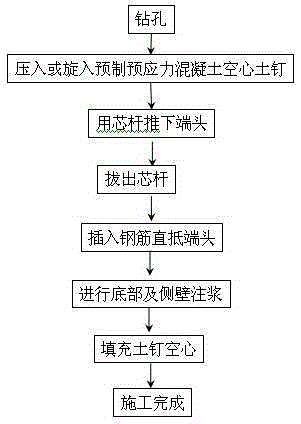
[0051] to combine Figure 1 to Figure 7 , the construction steps are introduced as follows:

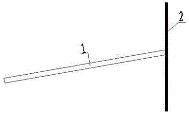
[0052] Step 1: Mechanical lead hole 1, the hole diameter is required to be no more than 60% of the diameter of the soil nail, and the angle between the soil nail hole and the horizontal angle is 10°. See the schematic diagram of the section figure 2 shown;

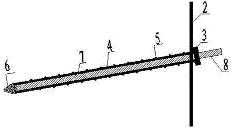
[0053] Step 2: Press the core rod 8 of the prefabricated prestressed concrete hollow soil nail into the lead hole. There are spiral blades 5 on the side wall of the soil nail. See image 3 shown;

[0054] Step 3: Use the mandrel to push the end away from the soil nail by 1.5m, then remove the mandrel, insert the steel bar 9 into the bottom of the soil nail until it reaches the end, see Figure 4 As shown, the corresponding sectional view is shown in Figure 5 shown;

[0055] Step 4: Insert the grouting pipe and perform bottom grouting. After the bottom grouting body 13 of the soil nail is formed, perform side wall grouting t...

Embodiment 2

[0060] It is basically the same as Example 1, except that the prefabricated prestressed concrete hollow soil nail has a wedge-shaped edge, and the cross-sectional schematic diagram after pushing down the end of the soil nail, pulling out the core rod, and inserting the steel bar is shown in Figure 8 shown, the corresponding section see Figure 9 As shown, the cross-sectional schematic diagram of the completed construction is shown in Figure 10 shown.

Embodiment 3

[0062] Step 1: Mechanical lead hole 1, the hole diameter is required to be no more than 60% of the diameter of the soil nail, and the angle between the soil nail hole and the horizontal angle is 10°. See the schematic diagram of the section figure 2 shown;

[0063] Step 2: Press the core rod 8 of the prefabricated prestressed concrete hollow soil nail into the lead hole. There are spiral blades 5 on the side wall of the soil nail. See image 3 shown;

[0064] Step 3: Fix the end, pull out the core rod, and carry out side grouting of soil nails. See the schematic diagram of the section Figure 11 shown.

[0065] Step 4: Use the core rod to push the end of the soil nail 1.5m away, then remove the core rod, insert the steel bar 9 into the bottom of the soil nail until it reaches the end, and perform grouting at the bottom of the soil nail. Figure 12 shown;

[0066] Step 5: After the grouting is completed, fill the hollow of the soil nail with plain concrete to form the core...


PUM


Abstract

The invention belongs to the technical field of construction engineering, and in particular relates to a prefabricated prestressed concrete hollow soil nail and a construction method. The construction steps of the present invention are as follows: (1) directly press or screw in the prefabricated prestressed concrete hollow soil nail, when the soil nail is difficult to press or screw in, mechanically guide the hole, requiring that the diameter of the hole is not greater than 60% of the diameter of the soil nail; (2) Press or screw the prefabricated prestressed concrete hollow soil nail into the lead hole, and the soil nail is inclined downward at an angle of 5-25 degrees; (3) Push the end of the soil nail more than 1m away from the core rod, and remove the core rod , Insert the steel bar until it reaches the end; (4) Grout the bottom and side walls of the soil nail; (5) Fill the hollow of the soil nail with plain concrete or soil. The invention has the advantages of little disturbance to the soil, good crack resistance, large bearing capacity, steel saving and the like.

Description

technical field [0001] The invention belongs to the technical field of construction engineering, and in particular relates to a prefabricated prestressed concrete hollow soil nail and a construction method. Background technique [0002] Today, with the rapid development of underground engineering, the enclosure structure needs to be further innovated and developed. At present, the enclosure structure mainly adopts support systems such as anchors and soil nails, that is, the lateral pressure of the soil acting on the enclosure structure is transmitted to the deep stable soil through the anchors and soil nails. The construction of soil nails mainly adopts mechanical hole forming, inserting steel bars, and pouring grout to form soil nails. The process is simple, but there are defects such as large disturbance to the soil, difficulty in ensuring the quality of soil nails, low bearing capacity, and large deformation. Hollow spiral steel nails are often screwed into the soil nail...

Claims


Application Information

Patent Timeline
Patent Type & Authority Patents(China)
IPC IPC(8): E02D5/74
CPCE02D5/74
Inventor 王国富
Owner JINAN RAILWAY TRANSPORT GRP CO LTD
Why Eureka
Try Eureka