Pressure stabilization compensation device and energy accumulator detection system with same

A compensating device and voltage stabilization technology, applied in the direction of fluid pressure actuating device, fluid pressure actuating system testing, mechanical equipment, etc. The effect of hydraulic shock, absorption of system pulsation and energy saving

Active Publication Date: 2015-04-22
YUN DONG LI INTELLIGENT MFG EQUIP CO LTD
View PDF10 Cites 10 Cited by
  • Summary
  • Abstract
  • Description
  • Claims
  • Application Information

AI Technical Summary

Problems solved by technology

[0003] The technical problem to be solved by the present invention is to provide a voltage stabilizing compensation device and an accumulator detection system for its application, to solve the problem of constant debugging and selection, and the inab

Method used


Image

  • Pressure stabilization compensation device and energy accumulator detection system with same
  • Pressure stabilization compensation device and energy accumulator detection system with same
  • Pressure stabilization compensation device and energy accumulator detection system with same

Examples


Embodiment 1

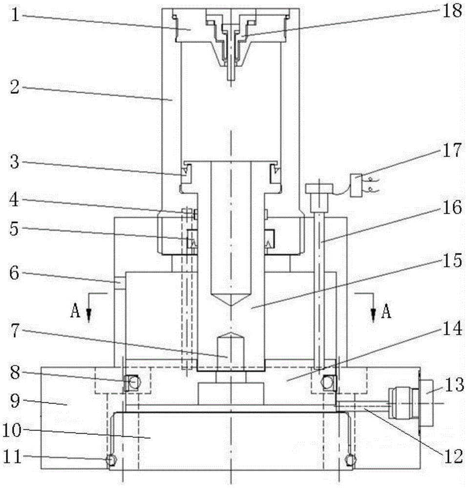
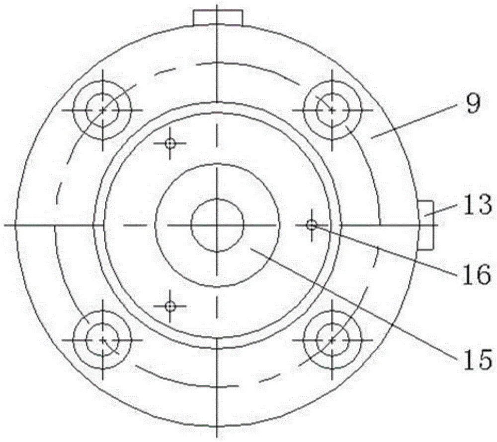
[0018] Such as figure 1 , figure 2 As shown, the voltage stabilizing compensation device includes a nitrogen gas spring, a master cylinder 9, a master cylinder end cover 10, a master cylinder piston body 14 and a gauge needle 16; the nitrogen gas spring includes a nitrogen cylinder end cover 1, a nitrogen cylinder body 2 and a nitrogen cylinder piston 15 , the outer wall of the nitrogen cylinder block 2 is provided with a scale, the nitrogen cylinder piston 15 is a cavity structure, the piston body of the nitrogen cylinder piston 15 cooperates with the inner chamber clearance of the nitrogen cylinder body 2 and is sealed by the nitrogen cylinder piston body oil seal 3, The piston rod of the nitrogen cylinder piston 15 stretches out from the bottom of the nitrogen cylinder body 2 and fits in a gap with the nitrogen cylinder body 2 and is sealed by the nitrogen cylinder piston rod oil seal 5 . A guide ring 4 is arranged between them, and the top of the nitrogen cylinder body ...

Embodiment 2

[0021] Such as figure 1 , figure 2As shown, the voltage stabilizing compensation device includes a nitrogen gas spring, a master cylinder 9, a master cylinder end cover 10, a master cylinder piston body 14 and a gauge needle 16; the nitrogen gas spring includes a nitrogen cylinder end cover 1, a nitrogen cylinder body 2 and a nitrogen cylinder piston 15 , the outer wall of the nitrogen cylinder block 2 is provided with a scale, the nitrogen cylinder piston 15 is a cavity structure, the piston body of the nitrogen cylinder piston 15 cooperates with the inner chamber clearance of the nitrogen cylinder body 2 and is sealed by the nitrogen cylinder piston body oil seal 3, The piston rod of the nitrogen cylinder piston 15 stretches out from the bottom of the nitrogen cylinder body 2 and fits in a gap with the nitrogen cylinder body 2 and is sealed by the nitrogen cylinder piston rod oil seal 5 . A guide ring 4 is arranged between them, and the top of the nitrogen cylinder body 2...


PUM


Abstract

The invention discloses a pressure stabilization compensation device. The bottom of a nitrogen cylinder body is installed on the top of a master cylinder, the piston rod extension end of a nitrogen cylinder piston extends into the master cylinder and is fixed to a master cylinder piston body through a screw, the master cylinder piston body is in clearance fit with an inner cavity of the master cylinder and is sealed with master cylinder piston body oil seals, the bottom end of a hand is fixed to the master cylinder piston body, the top end of the hand penetrates out of a rod end chamber of the master cylinder, and the bottom of the master cylinder is in threaded connection with a master cylinder end cover and is sealed with end cover oil seals. When used as an energy accumulator, the pressure stabilization compensation device serves as an auxiliary power source, is used for system pressure maintaining or serves as an emergency power source, absorbs system pulses, alleviates hydraulic shock, is long in service life and low in cost and saves energy resources; when overpressure or insufficient pressure occurs, the hand or a warning device is observed, and safety is guaranteed.

Description

technical field [0001] The invention relates to the technical field of accumulators, in particular to a voltage stabilizing compensation device and an accumulator detection system applied thereto. Background technique [0002] With the development of hydraulic system research, more and more attention has been paid to accumulators, but the requirements of the system are also getting higher and higher, such as image 3 , Figure 5 As shown, most of the existing basic theories of spring accumulator 21 were established in the 1970s and 1980s, and were obtained through experience summarization. Many of these theories are empirical, neither standard nor unified , can only play a preliminary guiding role in the system design, and the actual use still depends on the continuous debugging and selection of the staff, and the existing structure of the spring accumulator 21 determines that after it is installed on the system, it cannot be used according to the system requirements. It ca...

Claims


Application Information

Patent Timeline
IPC IPC(8): F15B15/20F15B19/00F15B1/02
CPCF15B1/02F15B15/20F15B19/00
Inventor 姜子涵张艳东姜皓文
Owner YUN DONG LI INTELLIGENT MFG EQUIP CO LTD
Why Eureka
Try Eureka