Eureka AIR delivers breakthrough ideas for toughest innovation challenges, trusted by R&D personnel around the world.

LED secondary optical lens and manufacturing method thereof

A secondary optical lens and lens technology, which is applied in the field of optical lenses, can solve problems such as energy waste, affecting light output efficiency, and affecting the physical shape of injection molding products, and achieves the effect of uniform spot and accurate calculation

Active Publication Date: 2015-04-22
CHENGDU HERCULUX OPTOELECTRONICS TECH CO LTD
View PDF7 Cites 2 Cited by
  • Summary
  • Abstract
  • Description
  • Claims
  • Application Information

AI Technical Summary

Problems solved by technology

Most of the traditional optical lens design methods use the inner curved surface as a hemispherical surface, and the calculated outer curved surface appears concave near the 90° of the light. When designing the mold, it is necessary to adopt a symmetrical design to facilitate injection molding, but the symmetrical design will Affects the solid shape of the injection molded product at the mold seam
At the same time, in order to facilitate the installation of the lens, it is also necessary to design a certain height of the installation side. Such a design results in the inability to effectively utilize the light near the 90° of the light source, affecting the actual light output efficiency and causing energy waste.

Method used


Image

  • LED secondary optical lens and manufacturing method thereof
  • LED secondary optical lens and manufacturing method thereof
  • LED secondary optical lens and manufacturing method thereof

Examples


Embodiment 1

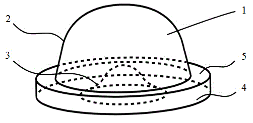
[0037] like Figure 1 to Figure 5 As shown, a LED secondary optical lens includes a lens body 1, and the middle part of the lens body 1 is provided with a convex lens outer curved surface 2, a lens inner curved surface 3 concave in the lens, and the convex lens outer curved surface 2 The starting end is connected with a pancake-shaped lens installation ring, the surface where the lens installation ring intersects with the outer curved surface of the lens is the installation surface 5, and the surface opposite to the installation surface is the base surface 4, and the convex lens outer surface 2 The outer curved surface curve 21 and the outer curved surface straight line 22 smoothly connected with the outer curved surface curve rotate around the central axis of the lens. The outer curved surface straight line 22 intersects the mounting surface 5, and the outer curved surface curve 21 intersects the lens central axis.

[0038] Since the part on the outer curved surface of the le...

Embodiment 2

[0049] like Figure 1 to Figure 7 As shown, a LED secondary optical lens includes a lens body 1, and the middle part of the lens body 1 is provided with a convex lens outer curved surface 2, a lens inner curved surface 3 concave in the lens, and the convex lens outer curved surface 2 The starting end is connected with a pancake-shaped lens installation ring, the surface where the lens installation ring intersects with the outer curved surface of the lens is the installation surface 5, and the surface opposite to the installation surface is the base surface 4, and the convex lens outer surface 2 The outer curved surface curve 21 and the outer curved surface straight line 22 smoothly connected with the outer curved surface curve rotate around the central axis of the lens. The outer curved surface straight line 22 intersects the mounting surface 5, and the outer curved surface curve 21 intersects the lens central axis.

[0050] Since the part on the outer curved surface of the le...


PUM


Abstract

The invention relates to the technical field of optical lenses and discloses an LED secondary optical lens. The LED secondary optical lens comprises a lens body, the lens body is provided with a convex lens positive camber and a lens negative camber concaved into the lens, the convex initial end of the lens positive camber is connected with a circular lens installation ring, the surface, crossed with the lens positive camber, of the lens installation ring is an installation face, the surface opposite to the installation face is a base face, the convex lens positive camber is formed by rotating a positive camber curve and a positive camber straight line connected with the positive camber curve around the center axis of the lens, the positive camber straight line is crossed with the installation face, and the positive camber curve is crossed with the center axis of the lens. No inwards concave part is generated in the lens positive camber, so that a mould is convenient to take out in the injection molding process of the lens; by designing the position of the cross point of the positive camber straight line and the installation face through calculating, light rays originally located between the base face and the installation face are fully utilized, light rays near the 90-degree emergent rays of a light source are effectively utilized, and light spots of emitted light rays are uniform.

Description

technical field [0001] The invention relates to an optical lens technology, in particular to an LED secondary optical lens and a manufacturing method thereof. Background technique [0002] As the concept of energy saving and environmental protection is deeply rooted in the hearts of the people, LED (Light Emitting Diode, Light Emitting Diode) has been more and more widely used due to its three advantages of energy saving, environmental protection and long life. As a light source, LED can theoretically consume only 10% of the energy consumption of incandescent lamps, which is 50% more energy efficient than fluorescent lamps. [0003] Since the light intensity distribution of the LED light source satisfies a Lambertian body and is extremely directional, it is necessary to design a secondary optical lens for it in order to achieve uniform lighting or other lighting distribution methods in actual use. At the same time, in order to save cost and use safely in the industry, the p...

Claims


Application Information

Patent Timeline
Patent Type & Authority Applications(China)
IPC IPC(8): F21V5/04F21Y101/02
CPCF21V5/046F21Y2101/00
Inventor 王金
Owner CHENGDU HERCULUX OPTOELECTRONICS TECH CO LTD
Why Eureka
Eureka Blog
Learn More