Aerodynamic heat flow measuring device and method for plume field of engine in vacuum chamber

A measuring device and engine technology, which is applied in the field of vacuum plume field, can solve the problems such as the difficulty of measuring aerodynamic heat in vacuum plume field, and achieve the effects of reducing the possibility of interference, avoiding damage, and short transmission distance

Inactive Publication Date: 2015-04-22
BEIHANG UNIV
View PDF6 Cites 17 Cited by
  • Summary
  • Abstract
  • Description
  • Claims
  • Application Information

AI Technical Summary

Problems solved by technology

[0007] In order to solve the problem that it is difficult to measure the aerodynamic heat of the vacuum plume field, the present invention proposes a set of measurement device and method for the aerodynamic heat flow of the engine plume field in the vacuum cabin, which can effectively solve the above problems and realize the large-scale, accurate measurement

Method used


Image

  • Aerodynamic heat flow measuring device and method for plume field of engine in vacuum chamber
  • Aerodynamic heat flow measuring device and method for plume field of engine in vacuum chamber
  • Aerodynamic heat flow measuring device and method for plume field of engine in vacuum chamber

Examples


Embodiment Construction

[0025] The present invention will be further described below in conjunction with accompanying drawing.

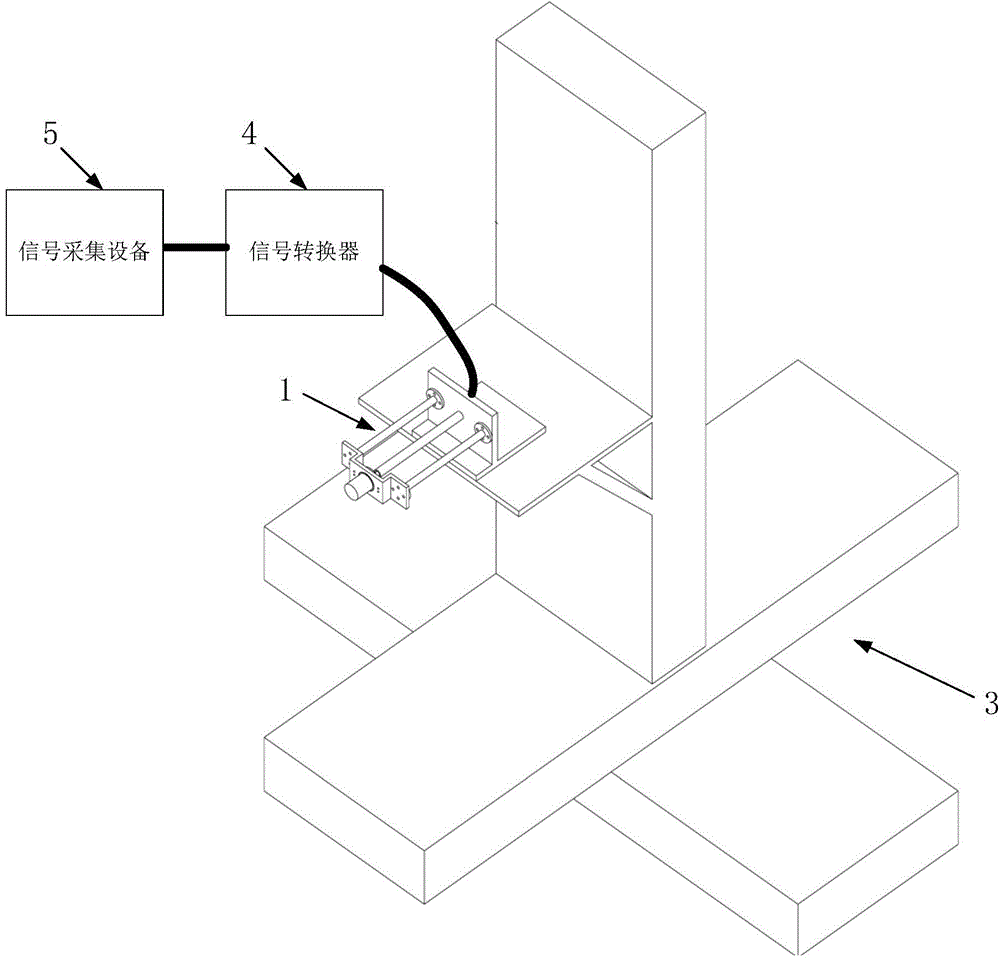
[0026] The present invention is aimed at the aerodynamic heat flow measurement device of the engine plume field in the vacuum chamber, including a bracket 1, a heat flow sensor 2, a three-dimensional moving device 3, a signal converter 4 and a signal acquisition device 5, such as figure 1 shown.

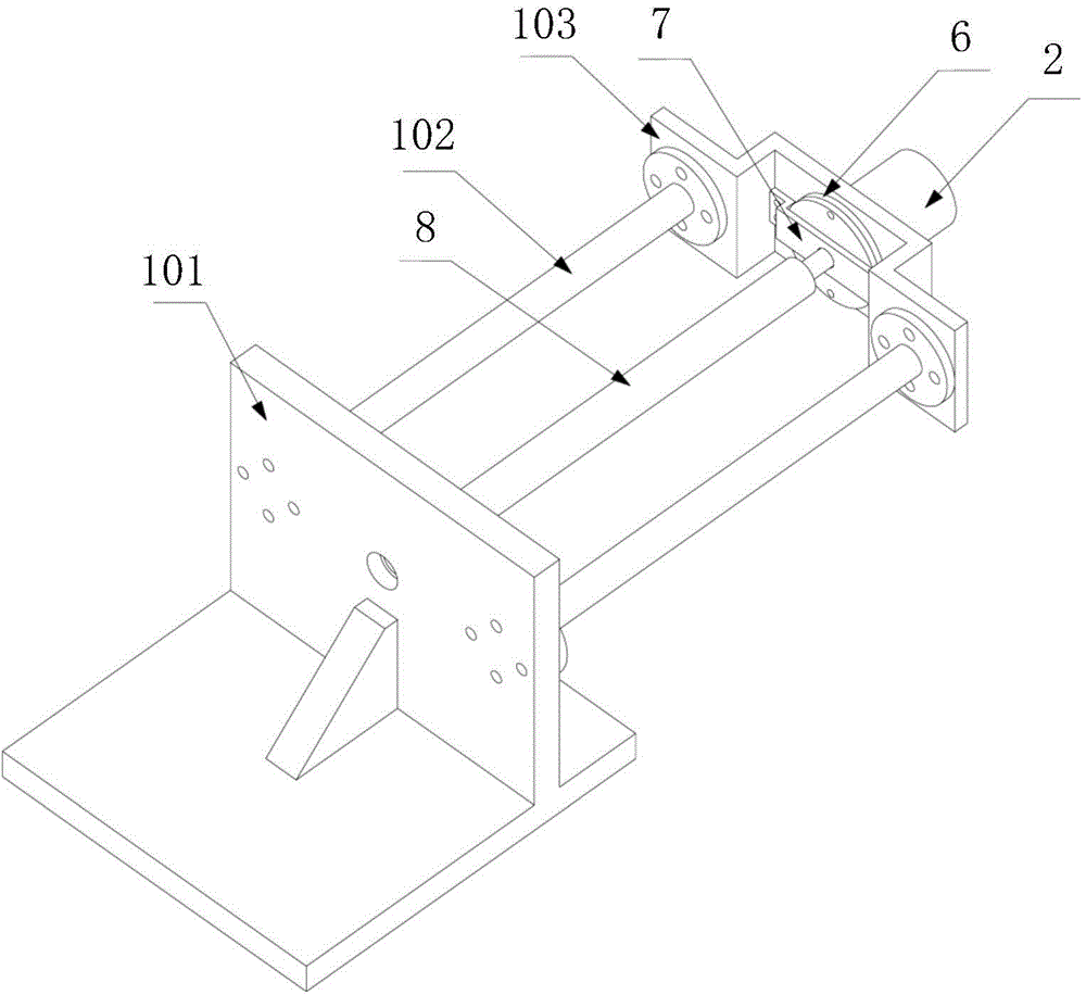
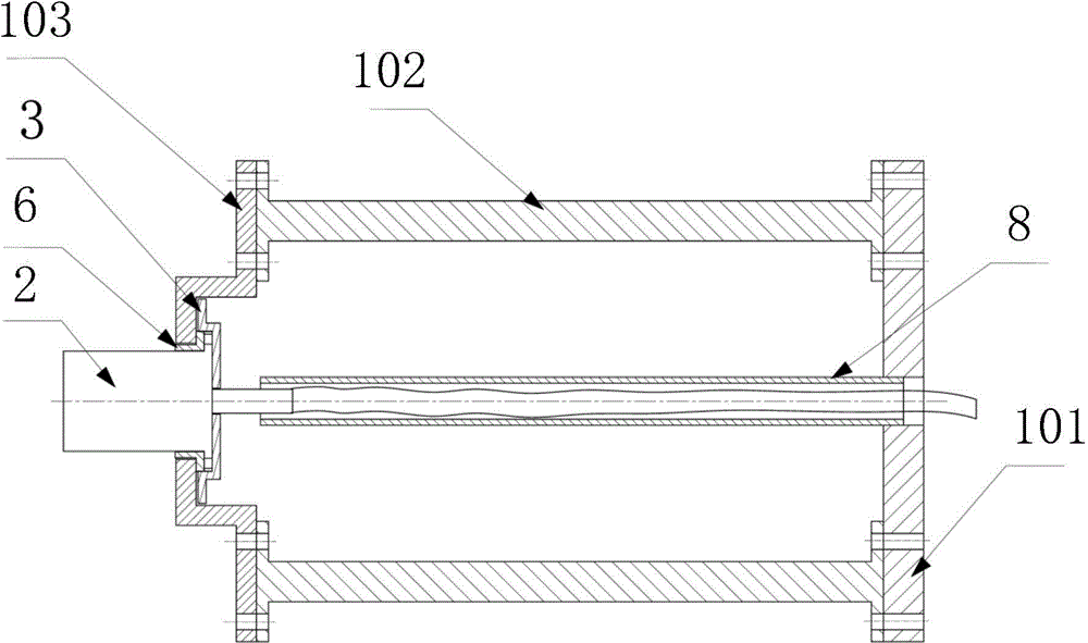
[0027] Wherein, the bracket 1 includes a mounting base 101 , a connecting rod 102 and a sensor fixing plate 103 . The mounting base 101 is made of stainless steel and has a horizontal fixing surface and a vertical connecting surface. There are two connecting rods 102 made of stainless steel with through holes processed at both ends for connecting the mounting base 101 and the sensor fixing plate 103 . The front ends of the two connecting rods 102 are fixedly connected to the vertical connection surface, and the rear ends are fixedly connected to the sensor fixing plate 103 , and...


PUM


Abstract

The invention discloses an aerodynamic heat flow measuring device and method for the plume field of an engine in a vacuum chamber. A support is fixedly mounted on an installation platform of a four-axis movement mechanism, the rear end of a heat flow sensor penetrates the rear side of the support, the heat flow sensor is sleeved with an insulated end cover, and an insulation sleeve is arranged between the heat flow sensor and the support. A signal line of the heat flow sensor is placed in a signal line protective piece, and connected to a signal converter by penetrating the front side surface of the support and then lead to a signal collector outside the vacuum chamber via a chamber-through flange. Voltage signals measured by the heat flow sensor are converted into current signals via the signal converter, and then collected by the signal collector, heat flow values are obtained by conversion according to the coefficient of the hot flow sensor, and thus, the aerodynamic heat flow of the plume field of the engine in the vacuum chamber is obtained. The method and device have the advantages that a three-dimensional movement device is cooperated, total-flow-field measurement is realized, and the problem that interference among sensors influences the flow-field form and further leads to inaccurate measurement is completely solved.

Description

technical field [0001] The invention relates to the field of mechanical design and aerodynamics, specifically, a set of aerodynamic heat flow measurement device and method for engine plume field in a vacuum cabin, which is applicable to vacuum plume field under all ground conditions. Background technique [0002] The attitude and orbit control engine is the power device on the spacecraft, and it is the core component necessary for the spacecraft to realize the functions of position maintenance, attitude control and orbit transfer. The plume-like flow field formed by the jet flow generated by the engine when it expands to the external vacuum environment is called the vacuum plume. The vacuum plume will have an aerodynamic thermal effect on the spacecraft, causing the surface temperature of the spacecraft to rise and the material to be damaged. Or some components will be damaged, which will reduce the performance of the working components, or lead to the failure of the flight ...

Claims


Application Information

Patent Timeline
Patent Type & Authority Applications(China)
IPC IPC(8): G01M9/06
Inventor 贺碧蛟张明星蔡国飙王文龙
Owner BEIHANG UNIV
Why Eureka
Try Eureka