Depth domain overall velocity model combination method and device

A technology of velocity model and fusion method, applied in the direction of seismic signal processing, etc., which can solve the problems of difficulty in picking up information, inability to reconstruct underground velocity information more accurately and comprehensively, etc.

Active Publication Date: 2015-04-22
PETROCHINA CO LTD
View PDF5 Cites 28 Cited by
  • Summary
  • Abstract
  • Description
  • Claims
  • Application Information

AI Technical Summary

Problems solved by technology

[0006] The seismic travel time tomography method only performs nonlinear inversion for the travel time information of a single wave, and cannot reconstruct the underground velocity information more accurately and comprehensively. It is more difficult to pick up information in the SNR region. In view of the shortcomings of the ...

Method used


Image

  • Depth domain overall velocity model combination method and device
  • Depth domain overall velocity model combination method and device
  • Depth domain overall velocity model combination method and device

Examples


Embodiment 1

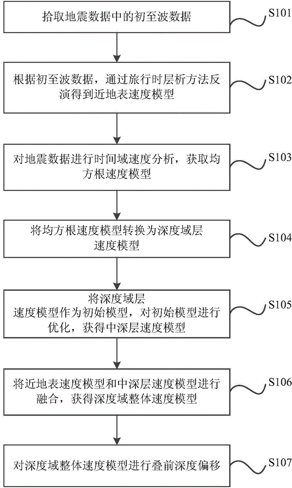
[0065] In view of this, the object of the present invention is to provide a method for fusion of the overall velocity model in the depth domain, figure 1 A flowchart of the method, comprising the following steps:

[0066] S101, picking up first arrival wave data in seismic data.

[0067] S102, according to the first arrival wave data picked up, a near-surface velocity model is obtained by inversion using a travel time tomography method.

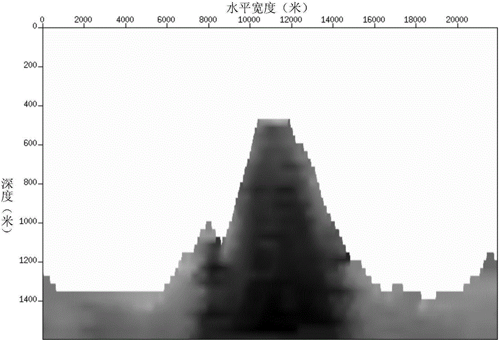
[0068] The establishment of high-precision near-surface models can be obtained by first-arrival traveltime inversion, first-arrival merging inversion, and Rayleigh wave inversion. In this example, the first-arrival traveltime inversion method is used to establish the near-surface velocity model , first pick up the first arrival time in the shot collection record of the target work area, and then use the first arrival travel time tomography to obtain the near-surface model, figure 2 is a near-surface velocity model obtained using first-arri...

Embodiment 2

[0087] The embodiment of the present application also provides a depth-domain overall velocity model fusion device, such as Figure 8 As shown, the device includes: picking unit 1, near-surface velocity model unit 2, root mean square velocity model unit 3, depth domain layer velocity model unit 4, mid-deep layer velocity model unit 5, velocity model fusion unit 6 and pre-stack depth Offset unit 7. in,

[0088] The picking unit 1 is used to pick up the first arrival wave data in the seismic data; the near-surface velocity model unit 2 is used to invert the near-surface velocity model through the travel time tomography method according to the first arrival wave data picked up; the root mean square The velocity model unit 3 is used to analyze the seismic data in time domain velocity to obtain the root mean square velocity model; the depth domain layer velocity model unit 4 is used to convert the root mean square velocity model into the depth domain layer velocity model; The mod...


PUM


Abstract

The invention provides a depth domain overall velocity model combination method and a device. The method comprises the following steps of collecting preliminary wave data in seismic data, obtaining a near earth surface velocity model through travel-time tomography inversion according to the collected preliminary wave data, conducting time domain velocity analysis on the seismic data to obtain a root-mean-square velocity model, converting the root-mean-square velocity model into a depth domain layer velocity model, obtaining a middle depth layer velocity model by adopting the depth domain layer velocity model as an initial model and optimizing the initial model, obtaining a depth domain overall velocity model by combining the near earth surface velocity model and the middle depth layer velocity model, conducting prestack depth migration on the depth domain overall velocity model. The depth domain overall velocity model combination method discloses a technology of combining the near earth surface velocity model and the middle depth layer velocity model, the depth domain overall velocity model of high precision is obtained, meanwhile, the requirements for calculating cost in industrial production are met.

Description

technical field [0001] The invention belongs to seismic data processing technology, and in particular relates to a fusion method and device for an overall velocity model in a depth domain. Background technique [0002] Seismic wave velocity parameters run through the entire process of seismic data acquisition, processing and interpretation, and velocity plays a vital role in every link of seismic exploration. Therefore, it has always been a problem worthy of in-depth study in seismic exploration to obtain the propagation velocity of seismic wave in underground medium accurately. [0003] Seismic travel time tomography is currently a commonly used method to obtain seismic wave velocity. This method is based on the observed seismic travel time information and applies model reconstruction algorithms to invert important information such as the structure of the underground medium, velocity distribution, and elastic parameters. Acting method. The disadvantage of seismic travel t...

Claims


Application Information

Patent Timeline
IPC IPC(8): G01V1/28
Inventor 张才胡英首皓王春明徐凌李萌
Owner PETROCHINA CO LTD
Why Eureka
Try Eureka