
Laser automatic stripping device and stripping method of side-by-side wire sheath

A wire sheath, automatic stripping technology, applied in the direction of cable installation, cable installation device, line/collector parts, etc., can solve the problems of reducing efficiency, wasting manpower, increasing costs, etc. The effect of high product yield

Active Publication Date: 2016-10-12
SUZHOU SHUTIAN LASER
View PDF4 Cites 0 Cited by
  • Summary
  • Abstract
  • Description
  • Claims
  • Application Information

AI Technical Summary

Problems solved by technology

However, the existing laser wire stripping machine usually needs to manually remove the sheath after cutting the wire, which consumes manpower, increases the cost, and reduces the efficiency.

Method used


Image

  • Laser automatic stripping device and stripping method of side-by-side wire sheath
  • Laser automatic stripping device and stripping method of side-by-side wire sheath
  • Laser automatic stripping device and stripping method of side-by-side wire sheath

Examples


Embodiment Construction

[0035] The technical solutions of the present invention will be further described below in conjunction with the accompanying drawings and specific embodiments.

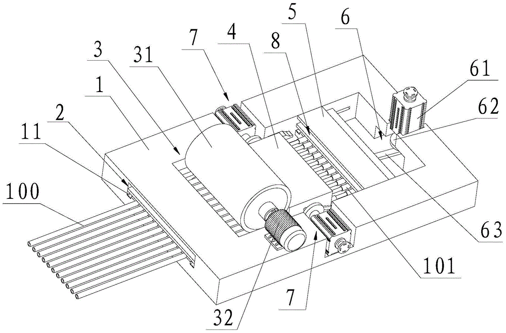
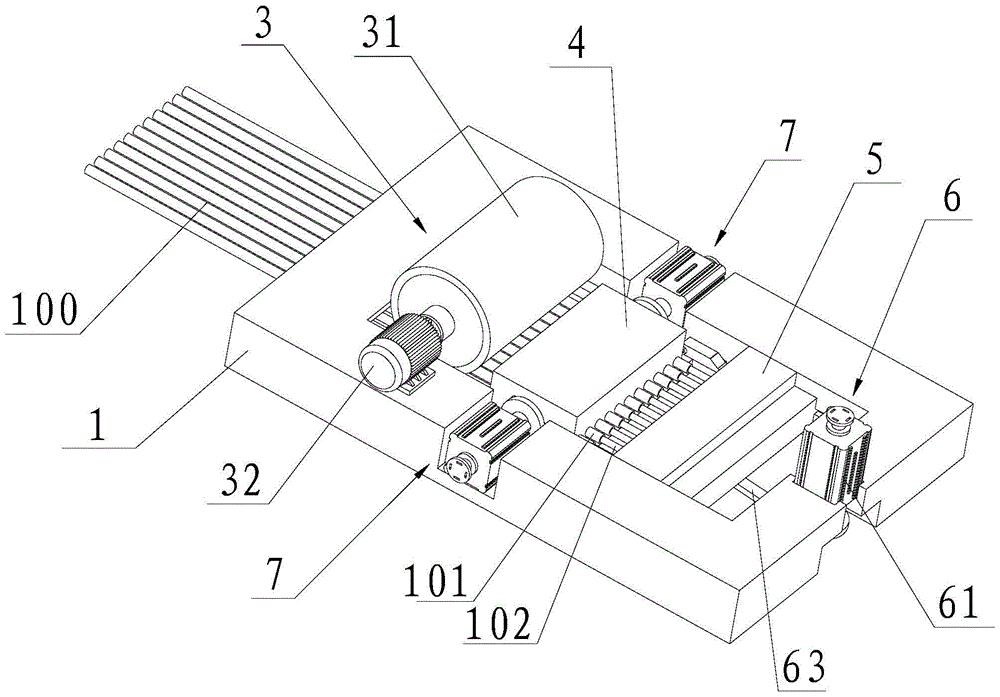
[0036] In the following definitions of direction, they are all defined according to the direction in which the wire is conveyed on the stripping device as a reference. The front and rear directions refer to the direction of wire transmission. 1 The left side of the center, and then the figure 1 The right side of the center, the left and right directions are the left and right sides of the wire.

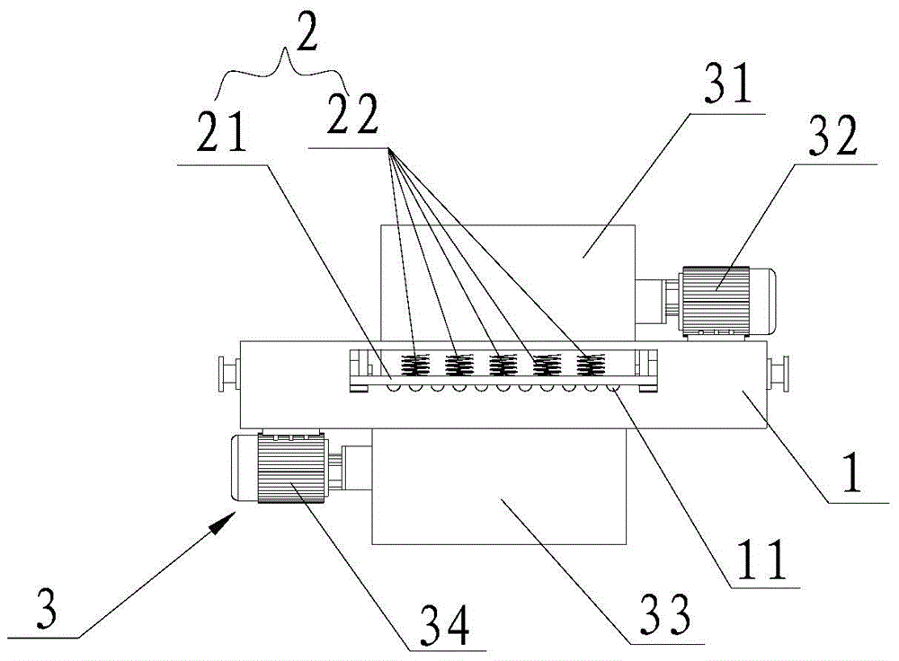
[0037] see picture 1 to 7 As shown, a laser automatic stripping device for side-by-side wire sheaths, the stripping device includes a fixed base 1 , the fixed base 1 The front opening is provided for multiple wires 100 Spouts that pass side by side in the front and back direction 11 , fixed base 1 The front end is also provided with multiple wires for this 100 fixedly pressed on the fixed bas...


PUM


Abstract

The present invention discloses a laser -automatic peeling device and divesticking method with a derivative line skin. Among them, after the laser cutting device is cut off, the wires are fixed to the wire.The clamping and pulling towards the direction of the wire is pulled away from the cut -off wire skin from the metal core of the wire to achieve the cutting and automatic peeling of the wire skin.The stripping device has a simple structure and is very convenient to operate. The automatic peeling of multiple wires that can be achieved and discharged and discharged.High yield.

Description

technical field [0001] The invention relates to a laser automatic stripping device and a stripping method for side-by-side conductor skins. Background technique [0002] When stripping the sheath of the wire, two stripping methods, traditional mechanical stripping and laser stripping, are mainly used. Mechanical stripping can realize the integration of wire sheath cutting and extraction, but because the jaws of the tool used contact the wire, it will generate a certain amount of extrusion and cutting force on the metal core on the wire, resulting in damage to the metal core. If the jaws are not in contact with the metal wire, the insulation cannot be stripped and cut cleanly. For the side insulation conductor composed of multiple layers of rayon fabric, mechanical stripping is even more difficult to meet the requirements. Laser wire stripping does not produce any mechanical extrusion and mechanical stress on the processing materials, especially for fine wires, the processin...

Claims


Application Information

Patent Timeline
Patent Type & Authority Patents(China)
IPC IPC(8): H01R43/28H02G1/12
CPCH01R43/28H02G1/1265
Inventor 杨桂林王明娣杜秋汤攀飞杭小琳
Owner SUZHOU SHUTIAN LASER
Learn More