
Micro-hotplate device and sensor comprising such micro-hotplate device

A technology of micro-hot plate and gas sensor, which is applied in the direction of instruments, scientific instruments, measuring devices, etc., and can solve problems such as non-existence

Active Publication Date: 2015-04-22
SGX SENSORTECH
View PDF13 Cites 22 Cited by
  • Summary
  • Abstract
  • Description
  • Claims
  • Application Information

AI Technical Summary

Problems solved by technology

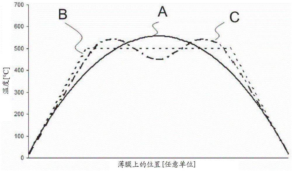
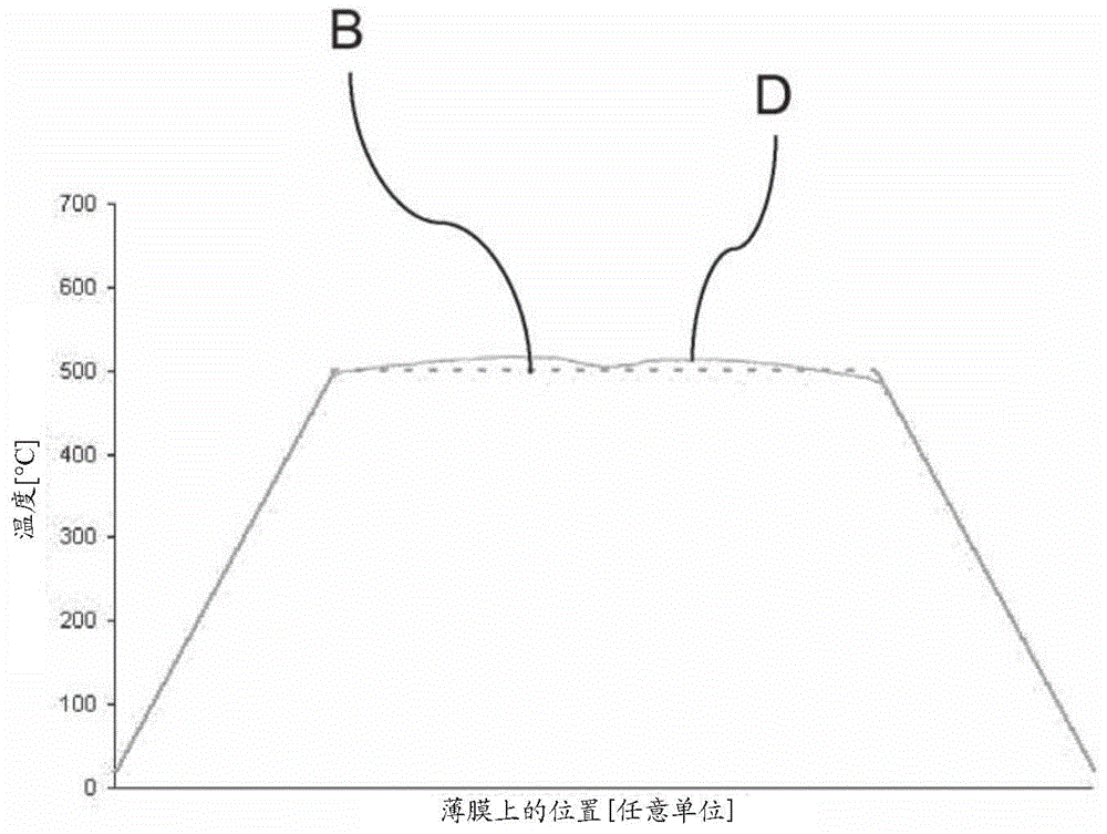
[0011] Therefore, currently there is no effective solution for achieving good temperature uniformity in the active area of ​​the micro-hotplate to improve the accuracy, efficiency and reliability of sensors using such micro-hotplates

Method used


Image

  • Micro-hotplate device and sensor comprising such micro-hotplate device
  • Micro-hotplate device and sensor comprising such micro-hotplate device
  • Micro-hotplate device and sensor comprising such micro-hotplate device

Examples


Embodiment Construction

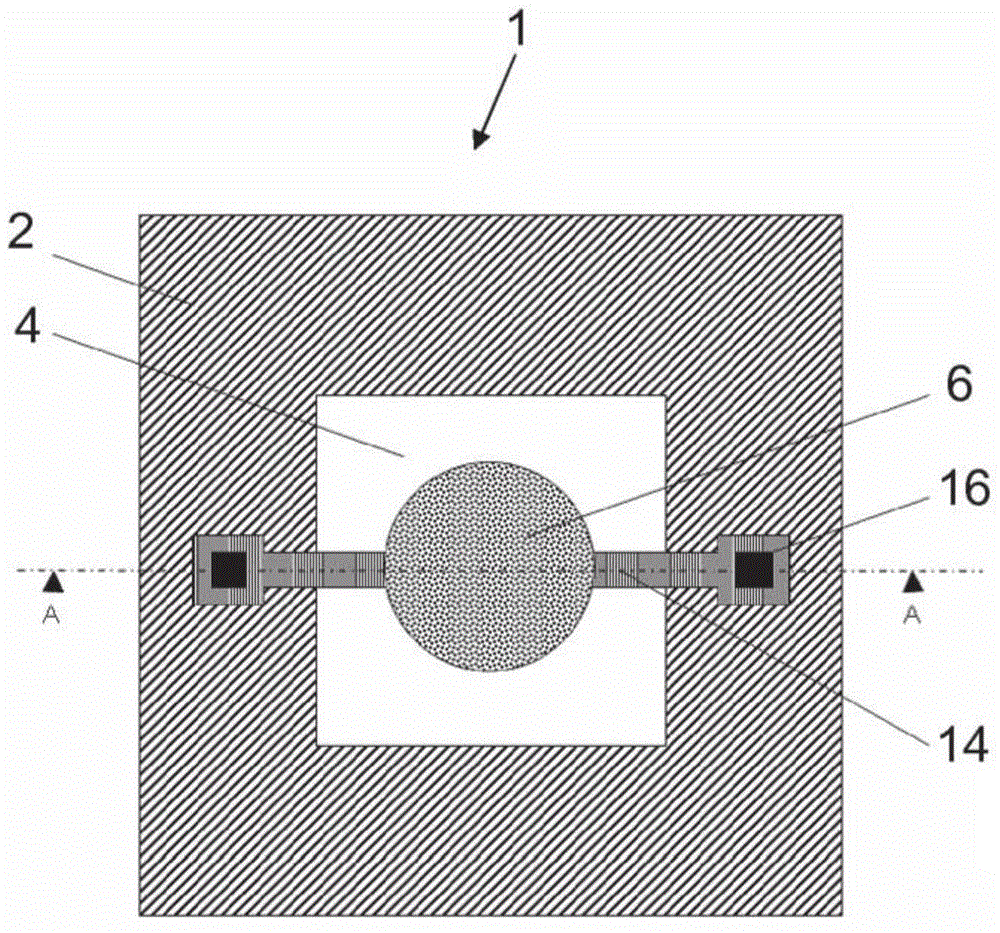
[0026] refer to figure 2 and image 3 , the micro-hot plate device 1 of the present invention comprises:

[0027] rigid frame 2;

[0028] a membrane 4 extending across said rigid frame 2;

[0029] an independent (ie not electrically connected) active region 6 comprising at least one active layer 8;

[0030] heating structures 10, deposited on the thin film 4 and designed to heat said active layer 8 to a given desired temperature;

[0031] a dielectric layer 12 for isolating the active layer from the heating structure; and

[0032] Contact tracks 14 and bonding pads 16 are used to connect the heating structure 10 .

[0033] The micro-hotplate is used for sensors, and more particularly for gas sensors. Depending on the sensor type, various combinations of passive and active layers can be deposited on the heating structure to achieve sensor functionality.

[0034] The lateral dimensions of the thin film 4 are generally in the range of 100 micrometers to several millimeter...


PUM

PropertyMeasurementUnit
sizeaaaaaaaaaa

Abstract

The present invention relates to a micro-hotplate device comprising a frame, a membrane, an active area comprising at least one active layer, and a heating structure designed to heat said active layer, said heating structure having concentric tracks and comprising inner tracks (20) and inner spaces (22) and outer tracks (24) and outer spaces (26) as being the one or two tracks and spaces located the furthest away from the center of the heating structure, characterized in that said outer tracks (24) are designed to be located closer to their neighboring tracks and / or are designed to have a width which is lower thanthose of the inner tracks (20), the width and the spacing of said inner tracks (20) being substantially constant.

Description

technical field [0001] The present invention relates to micro-hotplate devices. The invention also relates to sensors comprising such micro-hotplate devices, more particularly gas sensor devices. Background technique [0002] MEMS-based micro-hotplate devices are increasingly used in applications such as miniature flow sensors or gas sensors, where the detection principle is based on a temperature increase of the surrounding gas or an active functional layer. The small size of these microsensors has advantages when integrated into portable devices. However, in such applications, the important parameter is not only small size, but also low power consumption, because this important parameter has a direct impact on the battery life of portable instruments. To this end, extensive research and development has been carried out aimed at maximizing the efficiency of these sensors, i.e. maximizing their sensitivity, selectivity, stability and speed of response while minimizing the ...

Claims


Application Information

Patent Timeline
Patent Type & Authority Applications(China)
IPC IPC(8): G01N27/12G01N27/18
CPCG01N27/18G01N27/128Y10T436/214
Inventor 克莉丝汀·艾尔皮尼古拉斯·莫瑟尔
Owner SGX SENSORTECH
Learn More