Computer body layer photographing method and device

An imaging method and object technology, applied in the field of imaging, can solve problems such as unfavorable doctor identification and diagnosis, increase scanning time, image motion artifacts, etc., to avoid motion artifacts, save scanning time, and solve positioning problems.

Active Publication Date: 2015-04-29
浙江优医基口腔医疗器械有限公司
View PDF6 Cites 16 Cited by
  • Summary
  • Abstract
  • Description
  • Claims
  • Application Information

AI Technical Summary

Problems solved by technology

An obvious defect of this method is that obvious image artifacts are left at the splicing of the two 3D volume data, which is not conducive to the identification and diagnosis of doctors, and the CT scanning at the two positions requires additional moving process of the scanning device, which increases the Overall scan time, prone to unwanted motion artifacts in images

Method used


Image

  • Computer body layer photographing method and device
  • Computer body layer photographing method and device
  • Computer body layer photographing method and device

Examples


Embodiment Construction

[0054] The technical solution of the present invention will be described in detail below in conjunction with the accompanying drawings. The embodiments of the present invention are only used to illustrate the technical solutions of the present invention without limitation. Although the present invention has been described in detail with reference to the preferred embodiments, those skilled in the art should understand that the technical solutions of the invention can be modified or equivalently replaced , without departing from the spirit and scope of the technical solution of the present invention, all of which shall be covered by the claims of the present invention.

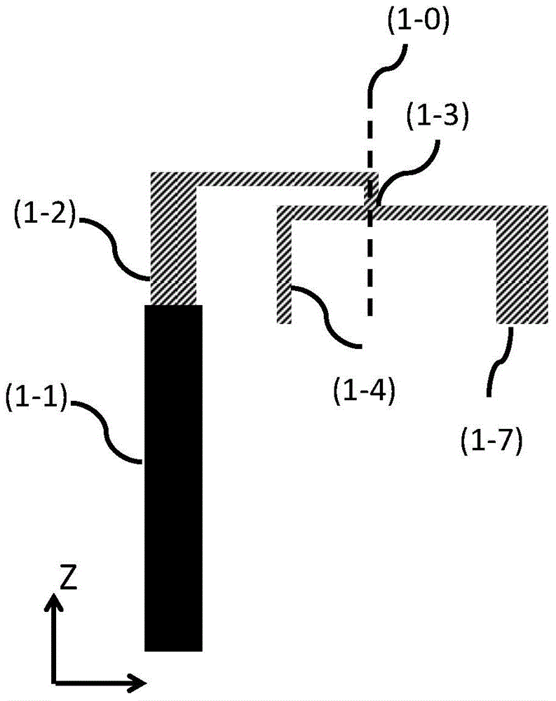
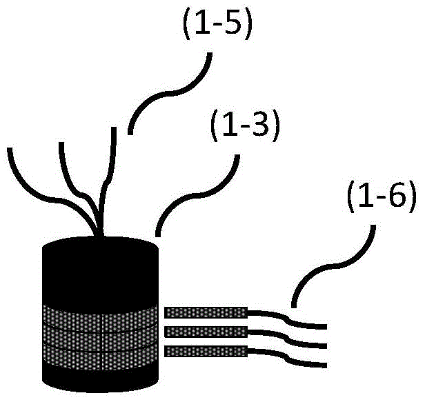
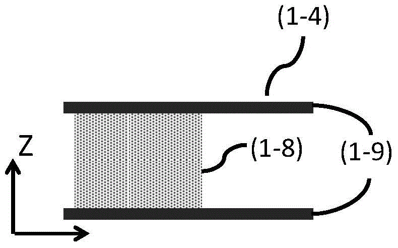
[0055] figure 1 It is a schematic structural diagram of an embodiment of a device for implementing the imaging method of the present invention, figure 2 for figure 1 A schematic structural diagram of an embodiment of the data signal transmission component in image 3 for figure 1 Schematic diagram of the s...


PUM


Abstract

The invention discloses an imaging method. The imaging method comprises the following steps: putting an object in a detection region, and biasing a detector; moving an imaging system along a longitudinal Z axis; enabling a ray source and a detector to synchronously move along the periphery of the object, scanning and acquiring data, and performing completion and faultage according to the data. According to the imaging method disclosed by the invention, the detector biasing and spiral trajectory scanning are combined to solve a problem that an image assembly method used by a conventional CT (computed tomography) imaging (particularly cone-beam CT imaging) generates artifact on the assembly image for the cone-beam CT covered by a long Z axis, so that a usage area of the detector is reduced, and the system cost is saved.

Description

technical field [0001] The present invention relates to an imaging method, in particular to a method for using a computer to perform photography on a tomography, and a device for implementing the method. Background technique [0002] Since the invention of the first CT prototype in 1971, CT imaging technology has played an important role in modern medical diagnosis. CT imaging equipment with a large imaging field of view is an urgent need for clinical applications. However, since CT detectors are expensive, the size of the detector will significantly affect the manufacturing cost of CT equipment. Configuring large-size detectors will significantly increase the manufacturing cost of CT imaging equipment. [0003] In order to obtain a larger CT imaging coverage volume, helical scanning is an ideal way to increase the imaging field of view. According to the search results of the academic paper database, German scientist Willi Kalender developed the first helical scanning CT ...

Claims


Application Information

Patent Timeline
Patent Type & Authority Applications(China)
IPC IPC(8): A61B6/03
CPCA61B6/027A61B6/4452A61B6/486A61B6/5241A61B6/5258A61B6/03G06T2207/10081A61B6/40A61B6/4208A61B6/5205G06T11/003G06T7/11G06T2211/416
Inventor 奚岩姚君李民旭
Owner 浙江优医基口腔医疗器械有限公司
Why Eureka
Try Eureka