
Deburring device and deburring method for cast cylinder bodies

A cylinder block and deburring technology, which is applied to the deburring device and deburring processing field of the casting cylinder block, can solve the problems of stamping damage of the cooling fins of the cylinder block, and it is difficult to completely remove the flash and burr, so as to ensure that the damage effect

Inactive Publication Date: 2015-04-29
温州市马锐汽缸制造有限公司
View PDF0 Cites 7 Cited by
  • Summary
  • Abstract
  • Description
  • Claims
  • Application Information

AI Technical Summary

Problems solved by technology

[0006] The purpose of the present invention is to overcome the stamping method used in the prior art to remove flashes and burrs on the casting cylinder block, which not only easily causes stamping damage to the die and the cooling fins of the cylinder block, but also makes it difficult to completely remove the flashes and burrs to provide a deburring device and deburring processing method for a cast cylinder block that can not only completely remove the flash and burrs on the cylinder block, but also ensure that the cylinder block and the die are not damaged

Method used

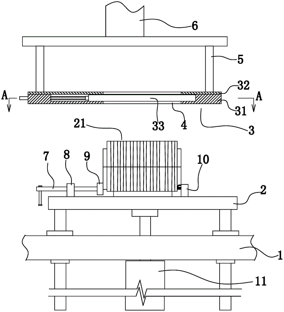

Image

  • Deburring device and deburring method for cast cylinder bodies
  • Deburring device and deburring method for cast cylinder bodies
  • Deburring device and deburring method for cast cylinder bodies

Examples


Embodiment 1

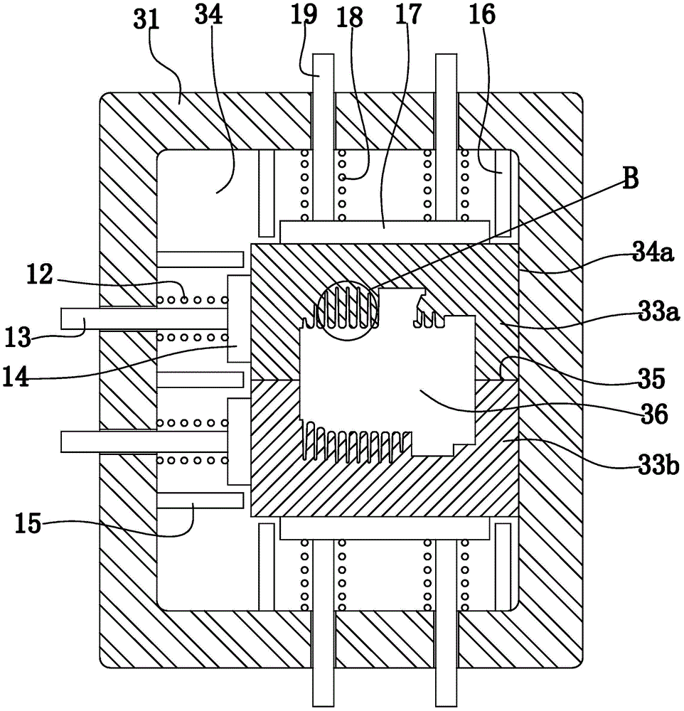
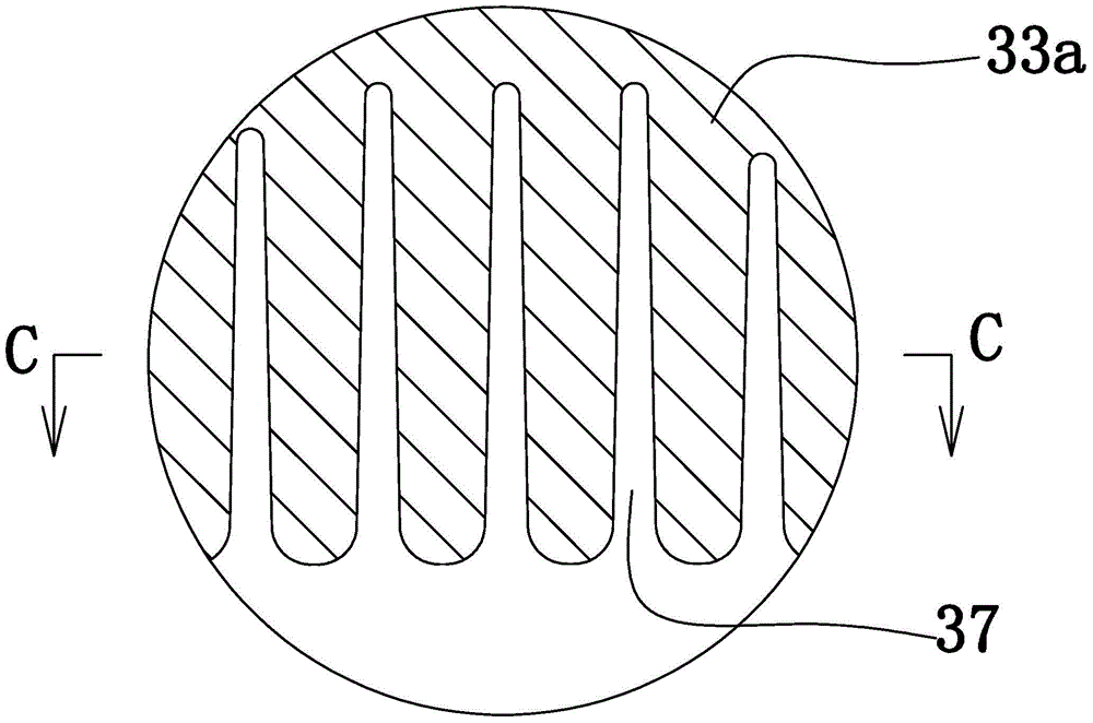
[0031] Embodiment 1: as figure 1 As shown, a deburring device for a cast cylinder block includes a frame 1, an installation platform 2, a floating pressing device 3 located above the installation platform, and a first lifting device arranged on the frame for lifting the installation platform 2 11 and the second lifting device 6 that is arranged on the frame and is used for lifting and lowering the floating pressing device 3. The top surface of the installation platform 2 is set horizontally. The bottom surface of the installation platform 2 is provided with a vertical guide rod. A vertical guide sleeve adapted to the vertical guide rod is arranged on the frame and below the installation platform. The first lifting device 11 is a lifting cylinder or a lifting oil cylinder. An installation frame 5 is arranged above the floating pressing device 3 . The second lifting device 6 is a lifting cylinder or a lifting oil cylinder arranged on the frame, and the piston rod of the lif...

Embodiment 2

[0043] Embodiment 2: A deburring processing method of a deburring device for a cast cylinder block, comprising the following steps in sequence:

[0044] a, Fix the cylinder block 21 on the installation platform 2 by clamping the tooling. After the cylinder block is fixed on the installation platform, the plane where the parting line 22 of the cylinder block is located is horizontally distributed, and the front and rear end surfaces of the cylinder block 21 are vertically distributed.

[0045] b, the first lifting device 11 drives the installation platform 2 and the cylinder block 21 to move upwards, and the upper part of the cylinder block is introduced into the press hole through the cylinder block inlet at the lower end of the press hole 36 until the mold parting line in the middle of the cylinder block 21 22. Pass through the upper port of the pressed hole gradually upwards from the inlet of the cylinder block, so that the parting line in the middle of the cylinder block is...


PUM


Abstract

The invention discloses a deburring device and a deburring method for cast cylinder bodies, and aims to provide a deburring device and method which can remove fins and burrs on the cylinder bodies thoroughly and guarantee that the cylinder bodies and a floating pressure cutting module are undamaged. The deburring device comprises a rack, a mounting platform, a floating pressure cutting device mounted over the mounting platform, a first lifting device arranged on the rack and used for lifting the mounting platform and a second lifting device used for lifting the floating pressure cutting device. A clamping tool is arranged on the mounting platform. The floating pressure cutting device comprises a floating pressure cutting module. A pressure cutting hole matched with the outer contours of the cylinder bodies is arranged in the floating pressure module. The deburring method includes: mounting one cylinder body on the mounting platform, driving the cylinder body to move upwards through the first lifting device, and enabling the joint line in the middle of the cylinder body to be located over an upper port of the pressure cutting hole; then, driving floating pressure cutting device to move upwards through the second lifting device, and thoroughly removing the fins and the burrs.

Description

technical field [0001] The invention relates to a deburring device for castings, in particular to a deburring device for a casting cylinder body and a deburring processing method using the device. Background technique [0002] At present, the castings formed by ordinary casting molds usually produce flashes and burrs at the parting line of the castings; The opening and closing impact is very easy to wear, and the wear of the parting surface will cause flashes and burrs on the parting surface at the parting line of the casting after the casting is cast. The flash and burrs at the parting line of the casting not only affect the processing of the casting, but also seriously affect the appearance quality of the product. [0003] Such as Figure 5 , Image 6 As shown, in an existing cast cylinder block, a plurality of cooling fins 23 are arranged on the outer surface of the cylinder block 21, and the parting line 22 of the cylinder block is arranged in the middle of the cylinde...

Claims


Application Information

Patent Timeline
IPC IPC(8): B22D31/00
CPCB22D31/00
Inventor 刘海波盛世文陈金鹤刘海茅许伟丰陈伟文
Owner 温州市马锐汽缸制造有限公司
Learn More