Intelligent trash removing protection device for submersible pump

A technology for protection devices and submersible pumps, applied to pump devices, parts of pumping devices for elastic fluids, pumps, etc., can solve the problem that the equipment cannot be used normally, no meaningful technical solutions are provided, and it is easy to get stuck in the sludge Conveying structure and other issues, to achieve the effect of easy maintenance and promotion, simple structure and clear working principle

Pending Publication Date: 2021-03-12
CHINA CONSTR FOURTH ENG DIV INSTALLATION ENG
View PDF5 Cites 0 Cited by
  • Summary
  • Abstract
  • Description
  • Claims
  • Application Information

AI Technical Summary

Problems solved by technology

The inventor of the present application has found that in practice, in the sludge discharged by the cleaning brush, there are mainly two parts, one part is the easy-to-fall-off part made of mud-water mixture, and the other part has fibrous tissue (such as hair, braided belt, etc.) ) are entangled into groups that are not easy to fall off. After brushing off the easy to fall off part, it is easy to cover the outside of the protective net again with the water flow. If the sludge conveying structure is only considered on the easy to fall off part, the difficult to fall off part is easy to get stuck. In the sludge conveying structure, the equipment cannot be used normally
There is no meaningful technical solution for this in the prior art

Method used


Image

  • Intelligent trash removing protection device for submersible pump
  • Intelligent trash removing protection device for submersible pump
  • Intelligent trash removing protection device for submersible pump

Examples


Embodiment approach

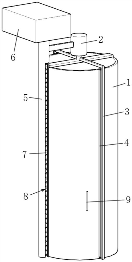
[0033] a. In the axial direction of the cylindrical structure, the length of the threaded delivery shaft 7 is greater than the length of the cylindrical structure.

[0034] b. In the axial direction of the cylindrical structure, the length of the cleaning brush 4 is smaller than the length of the cylindrical structure.

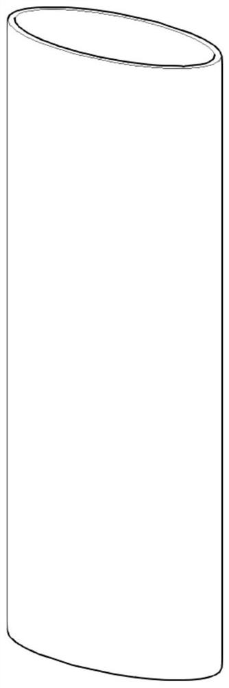
[0035] c. The cylindrical structure is a cylindrical structure;

[0036] d. The rotating rod 3 is driven by the driving motor 2, the rotating rod 3 is an L-shaped rod body, and the driving motor 2 is coaxial with the cylindrical structure.

Embodiment 1

[0038] Using the above scheme, if figure 1 As shown, the protective net cover 1 is a cylindrical structure, and a drive motor 2 is arranged at the center of the top of the protective net cover 1. The output shaft of the drive motor 2 coincides with the central axis of the protective net cover 1, and the output shaft of the drive motor 2 is provided with The L-shaped rotating rod 3 and the L-shaped rotating rod 3 are attached on the outer surface of the protective net cover 1, and an electric cleaning brush 4 is arranged at the bottom of the L-shaped rotating rod 3, and the electric cleaning brush 4 is connected to the outer surface of the protective net cover 1. Surface-attached, a delivery pipe 5 is provided on one side of the protective net cover 1, a dirt collection box 6 is provided on the top of the delivery pipe 5, a threaded delivery shaft 7 is provided in the delivery pipe 5, and an opening 8 is provided at the lower part of the delivery pipe 5 The opening 8 can corres...

Embodiment 2

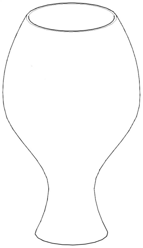
[0041] Such as figure 2 As shown, the protective net cover 1 is a cylindrical structure with unequal diameters, and other settings are the same as in Embodiment 1.

[0042] This embodiment is mainly suitable for submersible pumps that partially have raised structures.


PUM


Abstract

The invention provides an intelligent trash removing protection device for a submersible pump. A rotatable threaded conveying shaft is tightly attached and fixed along the outer wall of a cylindricalstructure body, and a trash removing brush capable of moving along the outer wall is arranged. The structures of the outer wall of the cylindrical structure body, the threaded conveying shaft and thetrash removing brush in the axial direction of the cylindrical structure body are consistent. Sludge at a water inlet of the submersible pump can be effectively cleaned away, smooth water inflow of the submersible pump is guaranteed, and therefore it is guaranteed that a water pump impeller is not damaged; the working principle is clear, the structure is simple, and maintenance and popularizationare easy; and automation and intelligence are facilitated.

Description

technical field [0001] The invention relates to an intelligent decontamination protection device for a submersible pump, which belongs to the technical field of building construction equipment. Background technique [0002] At present, the known submersible pump protection device is mainly composed of a skeleton and a filter screen, which can effectively isolate certain foreign objects from being sucked into the pump impeller. However, the protective device is a passive protection. When there are enough foreign objects adsorbed on the protective net, it is difficult for the water outside the protective net to enter. If the submersible pump is run at low temperature, it will cause the pump motor to burn out, and the damage of the submersible pump will cause no water to be used in the follow-up process or the phenomenon that the surrounding area will be submerged. [0003] The technical solutions of cleaning dirt in the prior art generally all directly brush away the sludge o...

Claims


Application Information

Patent Timeline
IPC IPC(8): F04D29/70F04D13/08
CPCF04D29/708F04D13/08
Inventor 吴家雄陈朝静杨晶杨乐乐陶豫苏魏李扬穆祥
Owner CHINA CONSTR FOURTH ENG DIV INSTALLATION ENG
Why Eureka
Try Eureka