Laser cleaning method for deoxidation

A laser cleaning and deoxidation technology, applied in the field of laser cleaning, can solve the problems of inability to adapt to the cleaning environment, complicated operation, and high cost, and achieve the effects of saving automation control costs, improving cleaning quality, and easy operation

Active Publication Date: 2022-08-09
咸亨电气技术(杭州)有限公司
View PDF7 Cites 0 Cited by
  • Summary
  • Abstract
  • Description
  • Claims
  • Application Information

AI Technical Summary

Problems solved by technology

This method is complicated to operate, the cost is high, and it cannot adapt to the complex cleaning environment.

Method used


Image

  • Laser cleaning method for deoxidation
  • Laser cleaning method for deoxidation
  • Laser cleaning method for deoxidation

Examples


Embodiment Construction

[0045] The present invention will be further described below with reference to the accompanying drawings and embodiments. However, this should not limit the protection scope of the present invention.

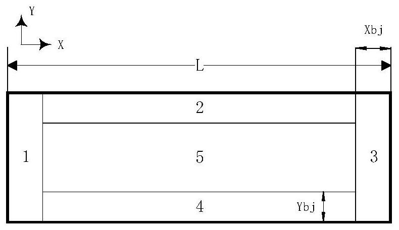
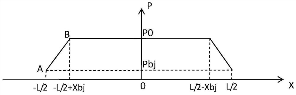
[0046] Terms such as "preset power", "boundary power", "X boundary", "Y boundary", and "middle region" in the embodiments of the present invention are only simplified descriptions for facilitating understanding of the present invention, rather than indicating or implying The referred structures, features, devices or elements must have the specific terminology or positional relationship, and therefore should not be construed as limiting the invention.

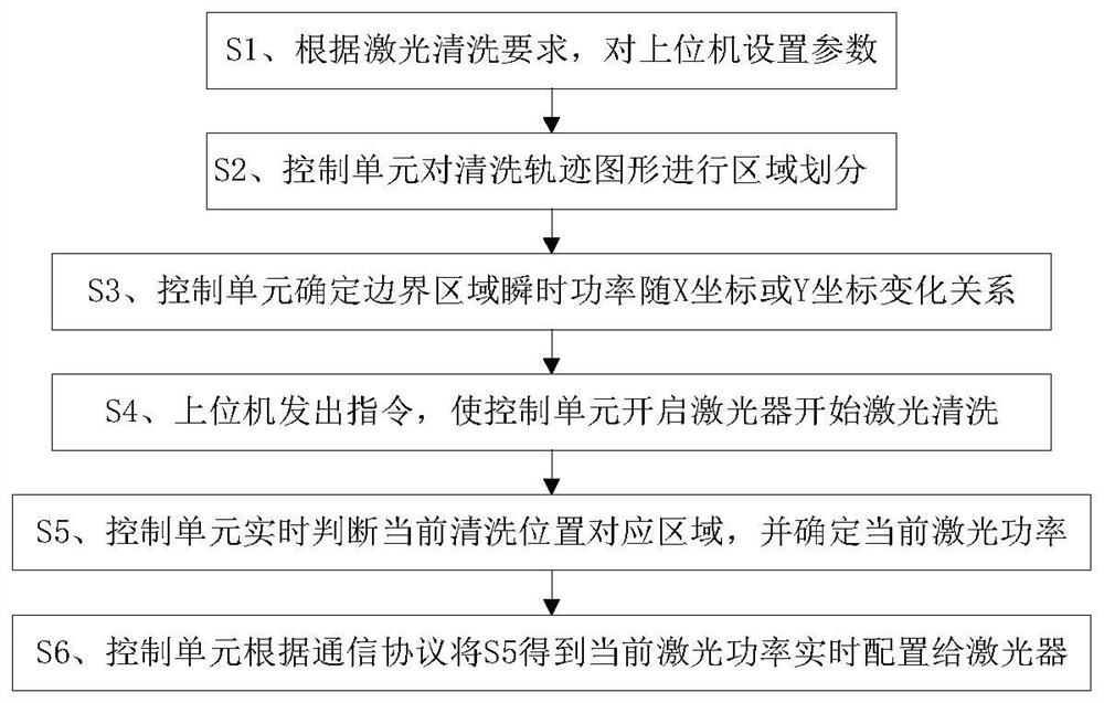
[0047] The laser cleaning device in this embodiment is a hand-held cleaning machine, and the cleaning object is the rust on the surface of the steel plate. The specific steps are as follows:

[0048] 1) The upper computer sets the parameters, and sets the cleaning trajectory as a spiral trajectory. The length and width of the tr...


PUM


Abstract

A laser cleaning method for deoxidation, comprising the steps of: setting parameters for an upper computer according to laser cleaning requirements; a control unit dividing a cleaning track pattern into regions; The machine sends an instruction to make the control unit turn on the laser to start laser cleaning; the control unit judges the area corresponding to the current cleaning position in real time, and determines the current laser power; the control unit configures the obtained laser power to the laser according to the communication protocol. The invention can effectively realize deoxidation, improve the cleaning quality, avoid damage to the substrate, is easy to operate, can adapt to different cleaning environments, saves automation control costs, and improves cleaning efficiency. This method can be widely used in laser cleaning.

Description

technical field [0001] The invention relates to a laser cleaning method, in particular to a deoxidized laser cleaning method. Background technique [0002] Laser cleaning is to overcome the bonding force between the material to be cleaned and the substrate through the interaction between the laser with a high energy density and the substance, and the force generated by the energy conversion to remove the material to be cleaned and the substrate. A new type of cleaning technology that removes contaminants from the surface of the material and achieves the purpose of cleaning. [0003] During the laser cleaning process, the galvanometer motor must have an acceleration or deceleration process when changing directions, resulting in too dense laser spots in the area corresponding to acceleration and deceleration. In the previous cleaning method, the laser power was constant during the cleaning process, which led to an increase in the temperature of the area corresponding to accel...

Claims


Application Information

Patent Timeline
Patent Type & Authority Patents(China)
IPC IPC(8): B08B7/00B08B13/00
CPCB08B7/0042B08B13/00Y02P10/20
Inventor 施蕾吕德亮陈丽明
Owner 咸亨电气技术(杭州)有限公司
Why Eureka
Try Eureka