Gate type plate shearing machine

A shearing machine and gate-type technology, which is applied in the field of machine tools, can solve problems such as machining errors of the fuselage, broken double-ended studs, and double-ended studs deviate from the center position, and achieve the effect of meeting the shearing requirements

Active Publication Date: 2015-04-29
江苏扬力液压装备有限公司
View PDF7 Cites 5 Cited by
  • Summary
  • Abstract
  • Description
  • Claims
  • Application Information

AI Technical Summary

Problems solved by technology

[0003] In actual use of this device, due to the reciprocating motion of the tool holder and the huge vibration during the shearing process, the threaded connection between the oil cylinder and the stud is prone to loosening, causing the tool holder to fall off
Also due to the machining error of the fuselage, it is easy to cause the double-ended stud to deviate from the center position when it penetrates into the mounting hole of the tool holder, resulting in breaking the double-ended stud when adjusting the shear angle
Also, due to the parallel death of the Belleville springs, the spherical washers and ball bearings cannot move and produce abnormal noise

Method used


Image

  • Gate type plate shearing machine
  • Gate type plate shearing machine
  • Gate type plate shearing machine

Examples


Embodiment Construction

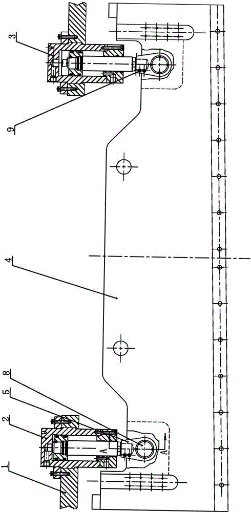
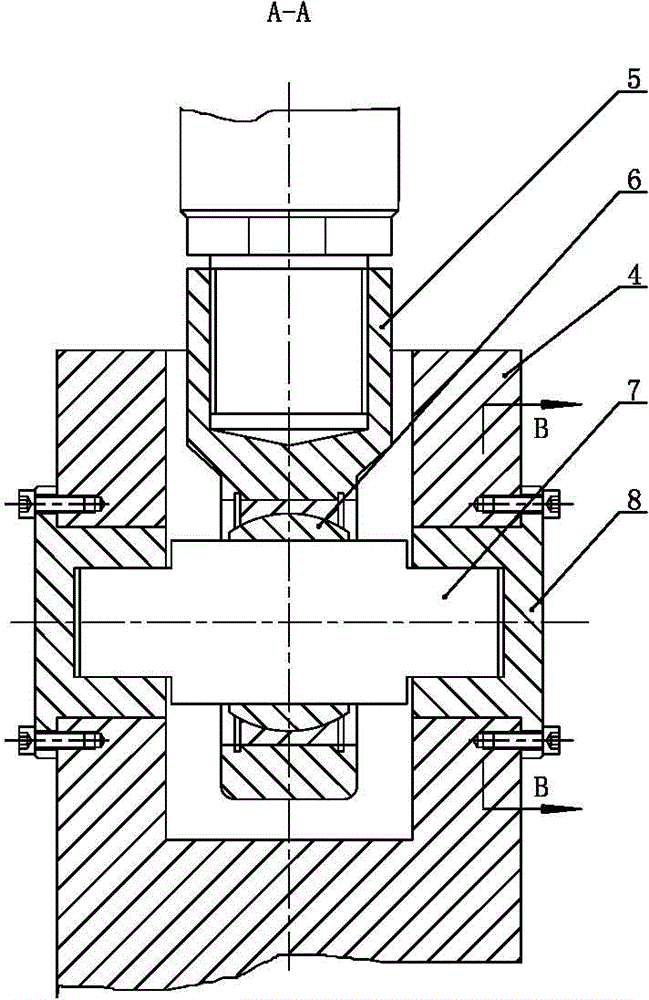
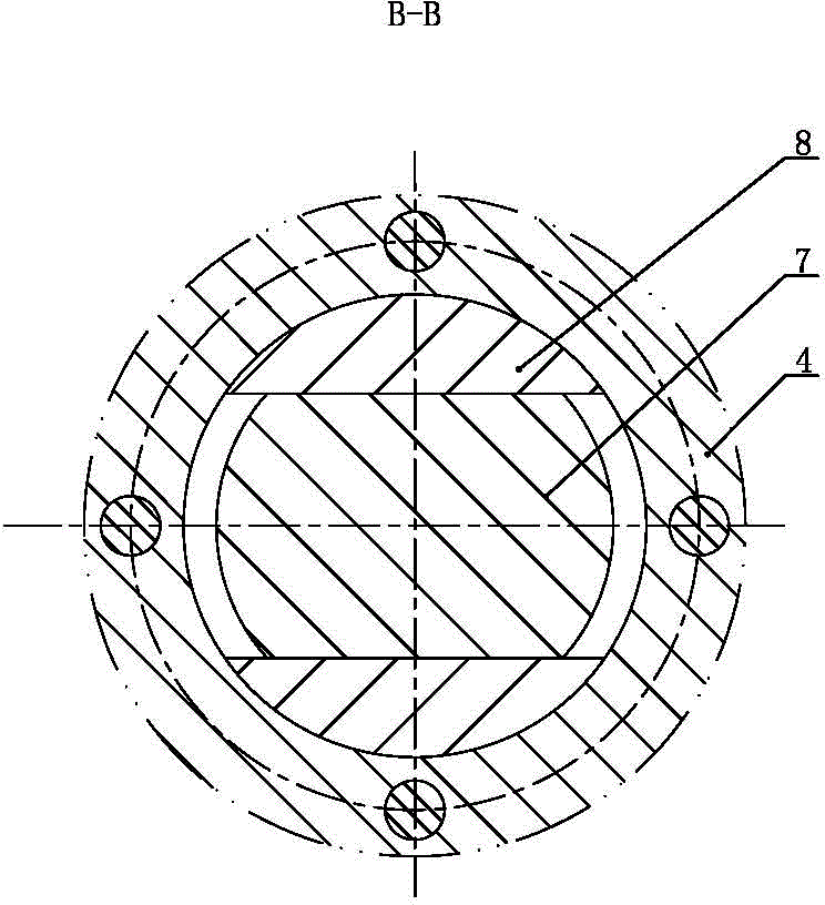
[0023] like Figure 1 to Figure 3 As shown, the gate type shearing machine of the present invention includes a bed 1, a material supporting mechanism and a shearing mechanism, and the shearing mechanism includes a left oil cylinder 2, a right oil cylinder 3 and a knife rest 4, and the left end of the knife rest 4 is connected to the left oil cylinder 2 The lower end of the piston rod, the right end of the tool holder 4 is connected to the lower end of the piston rod of the right oil cylinder 3, the cylinder bodies of the left oil cylinder 2 and the right oil cylinder 3 are respectively fixed on the bed 1, and the lower ends of the piston rods of the left oil cylinder 2 and the right oil cylinder 3 are respectively Connecting rod 5 is threadedly connected, and the lower end of connecting rod 5 is provided with connecting rod hole respectively, and the axis of connecting rod hole is perpendicular to the axis of piston rod and perpendicular to the plane where tool rest 4 is locate...


PUM

PropertyMeasurementUnit
heightaaaaaaaaaa

Abstract

The invention relates to a gate type plate shearing machine. The gate type plate shearing machine comprises a lathe bed, a material supporting mechanism and a shearing mechanism, wherein the left end of a tool post is connected with the lower end of a piston rod of a left oil cylinder, the right end of the tool post is connected with the lower end of a piston rod of a right oil cylinder, cylinder blocks of the left oil cylinder and the right oil cylinder are respectively fixed on the lathe bed, the lower ends of the piston rods of the left oil cylinder and the right oil cylinder are respectively screwed with connection rods through threads, a connection rod hole is formed in the lower end of each connection rod, the axis of each connection rod hole is vertical to the axis of each piston rod and vertical to a plane where the tool post is located, a ball bearing is installed in each connection rod hole, sliding shafts are respectively installed in inner holes of the ball bearings, the sliding shafts, the ball bearings and the lower ends of the connection rods are all located in installation holes of the tool post, two ends of each sliding shaft are respectively supported in two sliding holes of a sliding shaft seat, flange covers respectively stretched out towards the periphery are arranged on the outer end faces of the sliding shaft seats, and the flange covers are respectively connected onto the tool post. The gate type plate shearing machine can achieve adjustments of intervals of tool edges and shearing angles of the tool post, and transmits torque of the oil cylinders.

Description

technical field [0001] The invention relates to a shearing machine, in particular to a gate-type shearing machine, which belongs to the technical field of machine tools. Background technique [0002] The gate shearing machine is a device for cutting sheet materials. The traditional gate shearing machine includes a bed, a left cylinder, a right cylinder and a knife holder. The left end of the knife holder is connected to the lower end of the piston rod of the left cylinder, and the right end of the knife holder is connected to the At the lower end of the piston rod of the right oil cylinder, the cylinder bodies of the left oil cylinder and the right oil cylinder are respectively fixed on the left side and the right side of the bed. The upper end of the double-ended stud is connected with the piston rod of the oil cylinder, and the lower end of the double-ended stud penetrates into the mounting hole of the tool holder; the spherical washer and the ball bearing are respectively...

Claims


Application Information

Patent Timeline
Patent Type & Authority Applications(China)
IPC IPC(8): B23D33/00F15B11/16
Inventor 潘世宏朱道泉李祥
Owner 江苏扬力液压装备有限公司
Why Eureka
Try Eureka