Built-in machine tool spindle drive device

A technology of machine tool spindles and driving devices, which is applied in the direction of driving devices, metal processing machinery parts, metal processing equipment, etc., can solve the problems of high difficulty in manufacturing and processing electric spindles, thermal extension of the built-in motor of the spindle, etc., and achieve compact structure and lighten Effect of reducing weight and rotational inertia

Active Publication Date: 2015-04-29
NINGBO HAITIAN PRECISION MASCH CO LTD
View PDF8 Cites 1 Cited by
  • Summary
  • Abstract
  • Description
  • Claims
  • Application Information

AI Technical Summary

Problems solved by technology

However, the manufacturing and processing of the electric spindle is very difficult, and the built-in motor of the spindle has flaws in thermal extension and other issues, which cannot be solved well

Method used


Image

  • Built-in machine tool spindle drive device
  • Built-in machine tool spindle drive device
  • Built-in machine tool spindle drive device

Examples


Embodiment Construction

[0021] The present invention will be further described in detail below in conjunction with the accompanying drawings and embodiments.

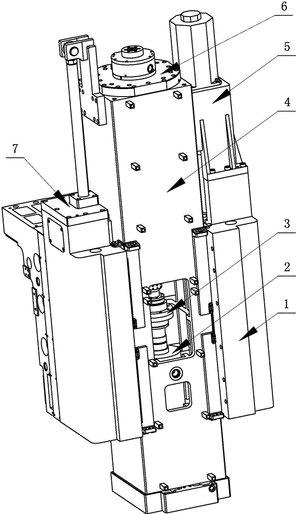
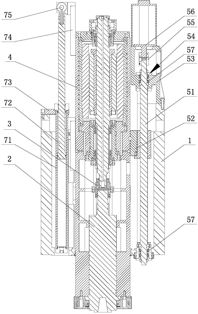
[0022] The built-in machine tool spindle drive device shown in the figure includes a built-in drive spindle assembly 6, a drive mechanism 5 and a coupling 3. The built-in drive spindle assembly 6 is installed on the inner side of the ram 4, and the ram 4 is installed on the saddle 1. , the driving mechanism 5 is installed on one side of the saddle 1, and the other side of the sliding saddle 1 is provided with a balance cylinder assembly 7, the driving mechanism 5 is connected with the ram 4, and the built-in driving spindle assembly 6 is connected to the mechanical spindle 2 through the coupling 3 Connected, the ram 4, the mechanical main shaft 2, the coupling 3 and the built-in driving main shaft assembly 6 form a ram assembly, driven by the driving mechanism 5, the ram assembly can slide up and down in the saddle 4.

[0023] The built-in dri...


PUM


Abstract

The invention discloses a built-in machine tool spindle drive device. The built-in machine tool spindle drive device comprises a built-in drive spindle component, a drive mechanism and a coupling, the built-in drive spindle component is arranged at the inner side of a ram, the ram is arranged on a slide saddle, the drive mechanism is arranged at one side of the slide saddle, the drive mechanism is connected with the ram, the built-in drive spindle component is connected with a mechanical spindle through the coupling, the ram, mechanical spindle, coupling and built-in drive spindle component form a ram component, and the ram component is capable of vertically sliding in the slide saddle under the drive of the drive mechanism. The built-in machine tool spindle drive device is compact in structure, the built-in drive spindle component replaces a traditional reduction gearbox, a spindle motor and a transmission shaft, and the weight of a ram moving component is reduced through using the built-in drive spindle component to drive the mechanical spindle; possible vibration caused by the reduction gearbox and transmission shaft is eliminated; the processing precision and running precision of the built-in drive spindle component are much lower than those of the electric spindle; the precision and rigidity of the mechanical spindle are reserved.

Description

technical field [0001] The invention relates to a drive device for a spindle of a numerically controlled machine tool, in particular to a built-in drive device for a spindle of a machine tool, which is used to optimize the ram parts of the spindle of a machine tool. Background technique [0002] For gantry machine tools, the main shaft forms are divided into mechanical main shaft and electric main shaft. The mechanical spindle is driven by a spindle motor, and its transmission chain is as follows: the power is generated from the spindle motor and transmitted to the gearbox through a coupling, and then the gearbox passes through a transmission shaft connected to the mechanical spindle for torque transmission, and finally transmitted to on the mechanical spindle. Among them, the mechanical main shaft is located at the front end of the machine tool ram, the main shaft motor and the reduction box are located above the ram, and the transmission shaft is located between the main ...

Claims


Application Information

Patent Timeline
Patent Type & Authority Applications(China)
IPC IPC(8): B23Q5/10
CPCB23Q5/10
Inventor 汪旭光谢瑞木宣文魁孙杰唐科平饶磊邵明辉王文杰
Owner NINGBO HAITIAN PRECISION MASCH CO LTD
Why Eureka
Try Eureka