Lathe spindle indexing locking mechanism

A technology of a lathe spindle and a locking mechanism, which is applied in automatic/semi-automatic lathes, turning equipment, metal processing machinery parts, etc. Simple to use effects

Active Publication Date: 2015-04-29
德州普利森机床有限公司
6 Cites 6 Cited by

AI-Extracted Technical Summary

Problems solved by technology

[0002] With the development of industrial fields such as automobiles, national defense, mining, agriculture, and construction machinery, higher and higher requirements are placed on the precision and efficiency of machined parts, but when processing evenly distributed keyways and threaded holes on the outer circle or end surface, Manual marking is required, and equipment such as milling machin...

Abstract

The invention provides a lathe spindle indexing locking mechanism. The lathe spindle indexing locking mechanism comprises an index plate which is fixed relative to a lathe spindle, an index plate positioning mechanism which achieves locking and unlocking of the index plate, a brake disc which is fixed relative to the lathe spindle, brake blocks which are respectively arranged on bilateral sides of the brake disc and a brake block driving mechanism which enable the two brake blocks to get close or be far from each other; an axis of the index plate and an axis of the brake disc and an axis of the lathe spindle are coincided. After a workpiece is lathed, positioning of the index plate is achieved through the index plate positioning mechanism, the brake block driving mechanism drives the two brake blocks to be close to the brake disc to achieve braking, the lathe spindle achieves locking positioning, a first key groove or hole is machined through a milling head or drill bit, the two brake blocks are separated after machining, the position of the index plate is unlocked, the spindle rotates to a next key groove or hole machining position of the workpiece, the index plate is positioned, the brake plate achieves braking to machine the next key groove or hole until all key grooves or holes are machined.

Application Domain

Precision positioning equipmentAutomatic conveying/guiding stock

Technology Topic

Drill bitBrake pad +3

Image

  • Lathe spindle indexing locking mechanism
  • Lathe spindle indexing locking mechanism
  • Lathe spindle indexing locking mechanism

Examples

  • Experimental program(1)

Example Embodiment

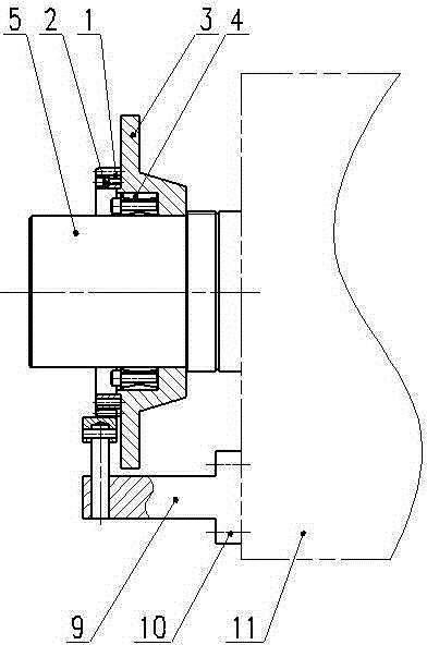
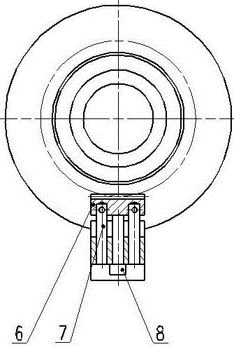
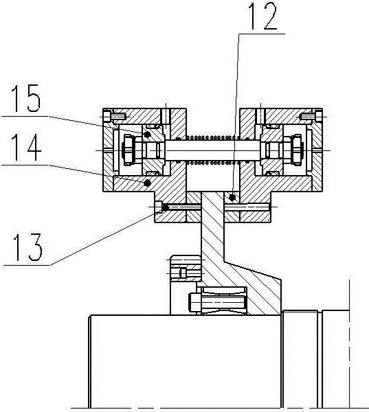
[0021] Such as Figure 1 to Figure 3 As shown, the lathe spindle indexing and locking mechanism includes an indexing plate fixed relative to the lathe spindle 5, an indexing plate positioning mechanism for locking and unlocking the position of the indexing plate, a brake disc 3 fixed relative to the lathe main shaft, and the brake discs respectively. Brake pads 12 on both sides and a brake pad drive mechanism that makes the two brake pads move closer or farther away. Both the axis of the index disc and the axis of the brake disc coincide with the axis of the main shaft of the lathe.
[0022] The index plate is the ring gear 1, and the index plate positioning mechanism includes a rack 6 matched with the ring gear and a rack moving mechanism that enables the rack to mesh or disengage from the gear ring. The rack moving mechanism includes a base 9 fixed on the headbox 11, an adjusting screw 8 passing through the base, and a guide post 7 for guiding the rack to move. The adjusting screw pushes the rack close to the ring gear and meshes with the ring gear. The base is fixed on the bedside box by screws 10. The adjusting screw extends radially along the main shaft of the lathe, and the guide column is arranged parallel to the adjusting screw. There are two guide posts, which are respectively located on both sides of the adjusting screw, and one end of each guide post is connected with the rack.
[0023] The brake pad drive mechanism includes two drive cylinders 14 that can be relatively close to or far away. Each drive cylinder has a piston 15 connected by the same piston rod. Each brake pad is fixed to a drive cylinder by screws 13 On the cylinder. The brake pads used for locking the spindle are fixed on the hydraulic cylinder by screws. The hydraulic system controls the direction of the piston, so that the hydraulic cylinders move towards each other to lock the brake discs and move away from each other to loosen the brake discs to realize the clamping and release of the spindle.
[0024] The brake disc is sleeved on the main shaft of the lathe, and the brake disc is relatively fixed by an expansion sleeve 4 arranged between the brake disc and the main shaft of the lathe.
[0025] Specifically, the index plate is fixed on the brake disc by screws 2.
[0026] Specifically, the number of teeth of the gear ring is an integer multiple of the number of key grooves or the number of holes evenly distributed in the circumferential direction on the outer circle or end surface of the workpiece. The number of graduations is related to the number of teeth of the ring gear, such as 24 or 12 equal divisions, and the number of ring gear teeth is an integer multiple of 24 or 12.
[0027] Specifically, the rack is located below the main shaft of the lathe, the adjusting screw is located below the rack, and the adjusting screw supports the rack.
[0028] The following is a specific example to introduce the method of using the present invention to process evenly distributed key grooves on the outer circle of a workpiece on a lathe:
[0029] The workpiece needs to be turned on the outer circle and equally processed 12 keyways on the outer circle. The gear ring has 72 teeth. After turning, the rack and the gear ring are meshed, and the lathe spindle is locked, and the first keyway is processed through the milling head. Then loosen the spindle of the turning machine, and record the first tooth that meshes, count 6 teeth and mesh again, lock the spindle of the lathe, process the second keyway, and so on. The workpiece is clamped once, with good accuracy and high efficiency.

PUM

no PUM

Description & Claims & Application Information

We can also present the details of the Description, Claims and Application information to help users get a comprehensive understanding of the technical details of the patent, such as background art, summary of invention, brief description of drawings, description of embodiments, and other original content. On the other hand, users can also determine the specific scope of protection of the technology through the list of claims; as well as understand the changes in the life cycle of the technology with the presentation of the patent timeline. Login to view more.

Similar technology patents

Fuel cell membrane electrode preparation process and hot-pressing mould thereof

PendingCN109301293ASimple processingReduce replacement costs
Owner:NANJING UNIV +2

Classification and recommendation of technical efficacy words

  • Increase productivity
  • Simple processing

Preparation method of super-retarding type polycarboxylate superplasticizer

ActiveCN103848944AIncrease productivityUniform product
Owner:KZJ NEW MATERIALS GROUP CO LTD

Method for preparing epoxide

ActiveCN101348472Ashort crystallization timeIncrease productivity
Owner:CHINA PETROLEUM & CHEM CORP +1
Why Eureka
Try Eureka