Drive support apparatus

A driving support and object technology, applied in the field of driving support devices, can solve problems such as the expansion of the detection area

Active Publication Date: 2015-04-29
TOYOTA JIDOSHA KK
View PDF22 Cites 13 Cited by
  • Summary
  • Abstract
  • Description
  • Claims
  • Application Information

AI Technical Summary

Problems solved by technology

However, if the sensing distance of a sonar sensor increases, its detection area increases accordingly, which me

Method used


Image

  • Drive support apparatus
  • Drive support apparatus
  • Drive support apparatus

Examples


Embodiment Construction

[0016] Hereinafter, embodiments will be described in detail with reference to the accompanying drawings.

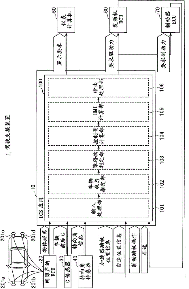
[0017] figure 1 is a block diagram illustrating one example of the system configuration of the driving support device 1 according to one embodiment.

[0018] exist figure 1 Among them, the driving assistance device 1 includes a driving assistance ECU 10 . The driving support ECU 10 includes a microprocessor including, for example, a CPU, a ROM storing a control program, a RAM storing calculation results, a timer, a counter, an input interface, an output interface, and the like.

[0019] The functions of the driving support ECU 10 can be realized by any hardware, software, firmware or any combination thereof. For example, any part or all of the functions of the driving support ECU 10 may be realized by ASIC (Application Specific Integrated Circuit), FPGA (Field Programmable Gate Array), or the like. Furthermore, any part or all of the functions of the driving support E...


PUM


Abstract

A drive support apparatus is disclosed, which includes a sonar sensor that transmits an ultrasonic wave to an object outside of a vehicle to obtain, based on a reflected wave thereof, object information related to a distance to the object; a controller that permits a first drive force limitation control when the distance to the object is longer than or equal to a predetermined distance, and permits at least one of a second drive force limitation control and an intervention brake control when the distance to the object is shorter than the predetermined distance, wherein a limitation level in the second drive force limitation control is higher than that in the first drive force limitation control.

Description

technical field [0001] The present invention relates to a driving support device. Background technique [0002] An obstacle detection device is known from Patent Publication No. 2007-333609. This known obstacle detection device compares a signal of a received wave of a sonar sensor amplified with a predetermined gain with a threshold value to determine the presence or absence of an obstacle. [0003] In general, sonar sensors have a shorter sensing distance than radar sensors using electromagnetic waves (eg, millimeter waves) or light waves (eg, laser light). In order to appropriately perform interventional braking control (or driving force limiting control) based on object information from the sonar sensor, it is beneficial to expand the sensing distance of the sonar sensor. However, if the sensing distance of a sonar sensor is extended, its detection area is correspondingly enlarged, which means that non-target objects that are not the detection target and would not othe...

Claims


Application Information

Patent Timeline
IPC IPC(8): B60R21/00B60T7/12G01S15/931
CPCB60T7/22B60T2201/022G01S15/931G01S15/46G01S15/876G01S15/08B60W2540/10B60W2520/10B60W30/09B60W10/06B60W10/184B60W2710/0605B60W2554/00B60W2554/801B60W2554/805
Inventor 高木俊宏
Owner TOYOTA JIDOSHA KK
Why Eureka
Try Eureka