
Blowout prevention valve

A blowout preventer and floating core technology, which is applied in wellbore/well valve devices, wellbore/well components, and earth-moving drilling and production, etc., can solve the problems of insufficient oil pipe blockage, difficult operation, and difficulty in blocking the liner. , to achieve the effect of accurate delivery, convenient operation and reliable blocking

Inactive Publication Date: 2015-04-29
PETROCHINA CO LTD
View PDF5 Cites 3 Cited by
  • Summary
  • Abstract
  • Description
  • Claims
  • Application Information

AI Technical Summary

Problems solved by technology

[0002] In the prior art, in the workover operations of oil and water wells with high pressure in the oil field, the diversity and complexity of the oil and water well completion strings have brought great difficulties to the workover, well completion and snubbing operations , the separate injection well passes through the eccentric water distributor, which makes it difficult to block the tail pipe; the new well is self-spraying or pumping, because there are perforating guns at the bottom, the tail pipe cannot be blocked during reoperation. The key is that the sealing, reliability and applicability of the plugging tool in the tubing determine the success or failure of the workover operation under pressure
[0003] The existing plugging tools in the tubing are mainly water conservancy delivery type and free delivery suppression type plugging, which will make the tubing The blockage is not in place, and the difficulty of passing tools and the need for ground facilities to cooperate with the delivery lead to difficult operations

Method used


Image

  • Blowout prevention valve
  • Blowout prevention valve

Examples


specific Embodiment approach

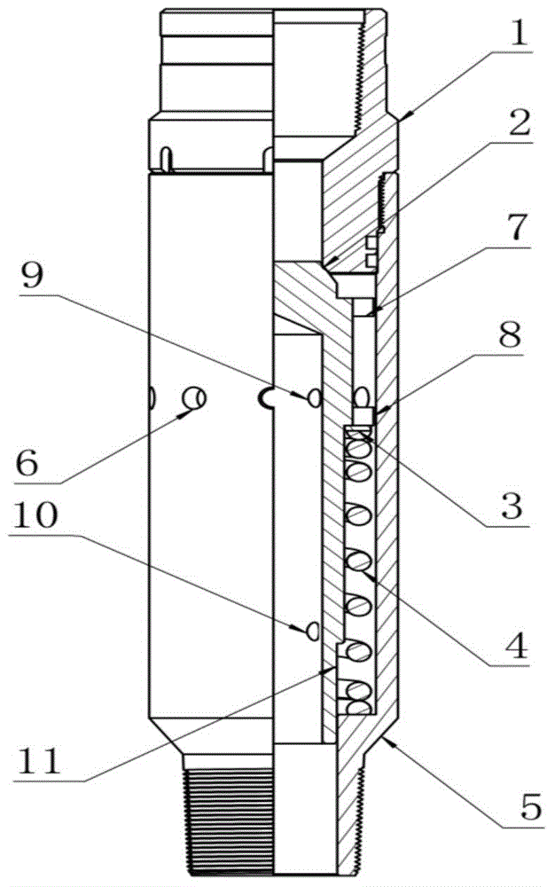
[0030] Such as figure 1 As shown: the blowout preventer of the present invention prevents blowout when lifting and lowering the pipe string and prevents blowout during re-operation. During the process of lifting and lowering the pipe string, the floating mandrel 2 moves upward due to the high-pressure flow at the bottom of the well. The fluid medium enters the blowout preventer valve from the lower end of the main body joint 5 or several outer wall guide holes 6 on the outer wall, but the floating mandrel 2 seals the step hole of the upper joint 1 of the blowout preventer valve to form a seal, which plays a role Anti-blowout effect.

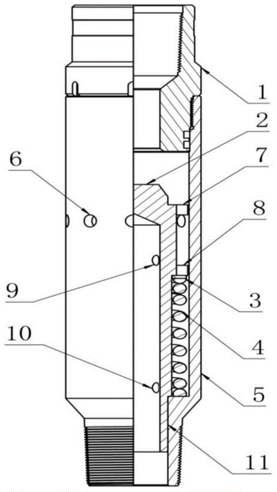
[0031] Such as figure 2 As shown: when the internal blowout preventer valve of the present invention is being injected or used, the pipe string is lowered to reach the predetermined position, and the oil pipe is being pressed until the floating mandrel 2 moves down, and the supporting and righting upper body 7, the supporting and righting lower...


PUM


Abstract

The invention provides a blowout prevention valve. The blowout prevention valve comprises an upper joint, a floating mandrel, an elastic piece, a main joint and a centering device, wherein the upper joint is connected with the main joint in a sleeving way, a first flow guiding hole is formed in the outer wall of the main joint, the floating mandrel, the elastic piece and the centering device are all arranged in the main joint, the elastic piece is arranged at the lower part of the centering device, the centering device is arranged at the lower part of the floating mandrel, a first medium flowing-out groove is formed in the centering device, a second flow guiding hole is formed in the medium flowing-out groove, and the second flow guiding hole is communicated with an inner hole in the floating mandrel. According to the blowout prevention valve disclosed by the invention, a tail pipe is blocked at a separate injection well passing eccentric water distributor; accurate throwing, reliable blocking, high adaptability and convenience in operation are realized when the blocking cannot be carried out by utilizing a pipe column of a new well while the new well is in flowing or is transformed into an oil pumping well.

Description

technical field [0001] The invention relates to the technical field of well workover, in particular to a blowout preventer valve. Background technique [0002] In the prior art, in the workover operations of oil and water wells with high pressure in the oil field, the diversity and complexity of the oil and water well completion strings have brought great difficulties to the workover, well completion and snubbing operations , the separate injection well passes through the eccentric water distributor, which makes it difficult to block the tail pipe; the new well is self-spraying or pumping, because there are perforating guns at the bottom, the tail pipe cannot be blocked during reoperation. The key is that the sealing, reliability and applicability of the plugging tool in the tubing determine the success or failure of the workover operation under pressure. [0003] The existing plugging tools in the tubing are mainly water conservancy delivery type and free delivery suppress...

Claims


Application Information

Patent Timeline
IPC IPC(8): E21B34/02E21B33/06
CPCE21B34/08
Inventor 张康卫彭军于锋袁龙向招祥孙永东崔臣滨罗永庆张宏峰姜艳王小兵刘刚苏江沈沛帆
Owner PETROCHINA CO LTD
Learn More