Decompression expansion trubo-generator set

A technology for generator sets and expansion turbines, applied to engine components, machines/engines, mechanical equipment, etc., can solve problems such as pipeline gas leakage, and achieve the effect of easy construction

Active Publication Date: 2015-04-29
SHENZHEN WISDOM ENERGY TECH CO
View PDF5 Cites 8 Cited by
  • Summary
  • Abstract
  • Description
  • Claims
  • Application Information

AI Technical Summary

Problems solved by technology

Due to the huge pressure difference between the inside of the pipeline and the outside of the pipeli

Method used


Image

  • Decompression expansion trubo-generator set

Examples


Embodiment Construction

[0016] Before describing the embodiments in detail, it should be understood that the present invention is not limited to the following or appended examples in this application. picture The detailed structure or arrangement of elements described in . The present invention can be implemented in other ways. Also, it should be understood that the phraseology and terminology used herein are for descriptive purposes only and should not be interpreted as limiting. The terms "including", "comprising", "having" and similar expressions used herein are meant to include the items listed thereafter, their equivalents and other additional items. In particular, when "a certain element" is described, the present invention does not limit the number of the element to one, but may also include a plurality.

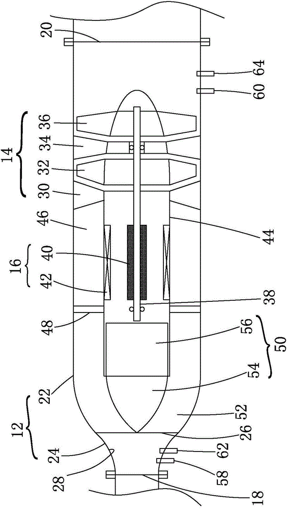
[0017] picture 1 is a simplified schematic diagram of an embodiment of a decompression expansion turbogenerator set picture . The generator set 10 includes a casing 12 , a turbine 14 an...


PUM


Abstract

The invention relates to a decompression expansion trubo-generator set, which comprises a shell and a turbine held in the shell. The shell comprises a pipeline air inlet and a pipeline air outlet. The generator set comprises a generator in drive connection with the turbine; the generator is held in the shell. A valve core can also be arranged on the upstream of the turbine; input pipeline air channels can be defined on the outer surface of the valve core and the inner surface of the shell; the valve core can move on the axial direction of the turbine relative to the turbine so as to change the cross section area of each input pipeline air channel.

Description

technical field [0001] The invention relates to a generating set using fluid to generate electricity, in particular to a decompression expansion turbine generating set using pipeline gas to generate electricity. Background technique [0002] In the prior art, there is a technology of using pipeline gas to drive a turbine and then drive a generator to generate electricity. In this known arrangement, the turbine is arranged in a closed casing, the inlet and outlet of which are connected to upstream and downstream piping. The generator is arranged outside the casing, and is connected to the turbine through the rotating shaft to generate electricity. Due to the huge pressure difference between the inside of the pipeline and the outside of the pipeline, there is a risk of pipeline gas leakage at the connection between the closed housing and the rotating shaft. Contents of the invention [0003] In view of this, this paper proposes a decompression expansion turbogenerator set ...

Claims


Application Information

Patent Timeline
IPC IPC(8): F01D15/10F01D25/24F01D17/10
Inventor 王崎文
Owner SHENZHEN WISDOM ENERGY TECH CO
Why Eureka
Try Eureka