Diaphragm type spring clutch

A spring clutch and diaphragm type technology, applied in the field of clutches, can solve the problems of large disassembly workload, small pressure plate lift, large separation force, etc., and achieve the effect of overcoming large ineffective stroke, simplifying the operating mechanism and improving fatigue life.

Inactive Publication Date: 2015-04-29
王一伊
View PDF3 Cites 2 Cited by
  • Summary
  • Abstract
  • Description
  • Claims
  • Application Information

AI Technical Summary

Problems solved by technology

The existing diaphragm type automobile clutch is composed of a pressure plate, a clutch cover, a diaphragm, an inner support ring and an outer support ring. The clutch cover is provided with several circumferentially evenly distributed flaps. When installing the inner support ring, the clutch cover is The inner support ring is installed between the clutch cover and the diaphragm when the tongue is turned and bent, the assembly workload is relatively large, the assembly efficiency is low, the inner support ring is prone to breakage, and the disassembly workload is large
Moreover, the rigidity of the ordinary diaphragm spring separation finger is poor, resulting in a large invalid separation stroke of the clutch assembly, a small lift of the pressure plate, and a large separation force, and the reliability of mechanical properties is low.
At the same time, there are problems such as heavy pedal force, difficult gear shifting, and early failure of the clutch on the whole vehicle

Method used


Image

  • Diaphragm type spring clutch
  • Diaphragm type spring clutch
  • Diaphragm type spring clutch

Examples


Embodiment Construction

[0012] The principles and features of the present invention are described below in conjunction with the accompanying drawings, and the examples given are only used to explain the present invention, and are not intended to limit the scope of the present invention.

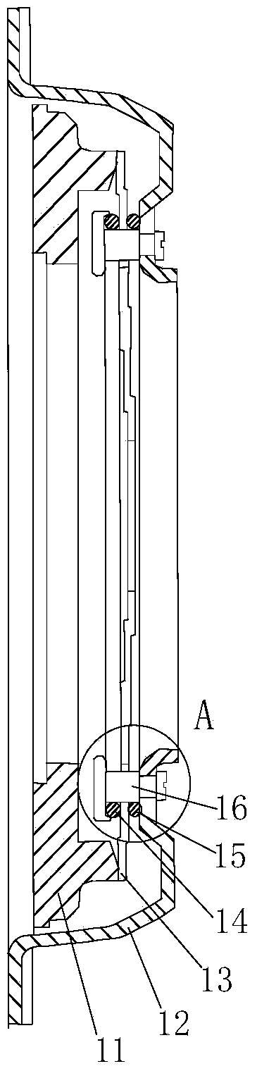
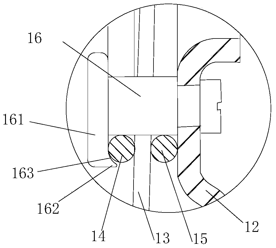
[0013] Such as figure 1 , figure 2 As shown, a diaphragm spring clutch includes a pressure plate 11, a clutch cover 12, a diaphragm 13, an inner support ring 14 and an outer support ring 15, and several diaphragm rivets 16 uniformly distributed in the circumferential direction. The left end of the rivet 16 is provided with a shoulder 161, and on the right end surface of the shoulder 161, a pointed protrusion 162 with the tooth tip facing the right is provided, and a concave arc surface 163 is provided on the pointed protrusion. The disc rivet 16 connects the inner support ring 14, the diaphragm 13, the outer support ring 15 and the clutch cover 12 from left to right in turn, and makes the diaphragm rivet 16 The c...


PUM


Abstract

The invention relates to a diaphragm type spring clutch. The diaphragm type spring clutch comprises a pressing plate, a clutch cover, a diaphragm, an inner supporting ring, an outer supporting ring and a plurality of diaphragm rivets, wherein the diaphragm rivets are uniformly distributed in the circumferential direction, shoulders are arranged at the left ends of the diaphragm rivets, pointed bulges with tooth tops facing rightwards are arranged on the right end surfaces of the shoulders, concave arc surfaces are arranged on the pointed bulges, the diaphragm rivets are used for sequentially connecting the inner supporting ring, the diaphragm, the outer supporting ring and the clutch cover together from left to right, and the concave arc surfaces on the diaphragm rivets are tightly attached to the inner supporting ring; the diaphragm comprises a diaphragm spring main body and separation fingers which are uniformly distributed on an inner ring of the diaphragm spring main body, and reinforcing ribs which are upwards convex are respectively arranged at the centers of the separation fingers along the radial direction. The diaphragm type spring clutch disclosed by the invention is simple in structure, convenient to assemble, disassemble and maintain, capable of overcoming the defect of large idle stroke of a clutch assembly and reducing a separating force of the clutch assembly, high in production efficiency, low in cost, safe and reliable.

Description

technical field [0001] The invention relates to the field of clutches, in particular to an automobile diaphragm spring clutch. Background technique [0002] The clutch is composed of a friction plate, a spring diaphragm, a pressure plate and a power output shaft. It is arranged between the engine and the gearbox, and is used to transfer the torque stored on the engine flywheel to the gearbox to ensure that the vehicle is transmitted to the gearbox under different driving conditions. The appropriate driving force and torque of the driving wheels belongs to the category of powertrain. The existing diaphragm type automobile clutch is composed of a pressure plate, a clutch cover, a diaphragm, an inner support ring and an outer support ring. The clutch cover is provided with several circumferentially evenly distributed flaps. When installing the inner support ring, the clutch cover is The inner support ring is installed between the clutch cover and the diaphragm by bending the t...

Claims


Application Information

Patent Timeline
Patent Type & Authority Applications(China)
IPC IPC(8): F16D13/58
Inventor 王一伊
Owner 王一伊
Why Eureka
Try Eureka