Elastic compensation device/group/bracket and absorption tower device

An elastic compensation and device group technology, applied in the direction of spring/shock absorber, shock absorber, gas shock absorber, etc., can solve problems such as inconvenient operation, and achieve a compact structure with convenient maintenance and replacement, compact structure and good shape structure. sexual effect

Inactive Publication Date: 2015-04-29
ZHONGYE-CHANGTIAN INT ENG CO LTD
View PDF13 Cites 13 Cited by
  • Summary
  • Abstract
  • Description
  • Claims
  • Application Information

AI Technical Summary

Problems solved by technology

[0006] The invention provides an elastic compensation device, which solves the technical problem that the elastic compensation device in the prior art is inconvenient to operate when the elastic preload is released during use

Method used


Image

  • Elastic compensation device/group/bracket and absorption tower device
  • Elastic compensation device/group/bracket and absorption tower device
  • Elastic compensation device/group/bracket and absorption tower device

Examples


Embodiment 1

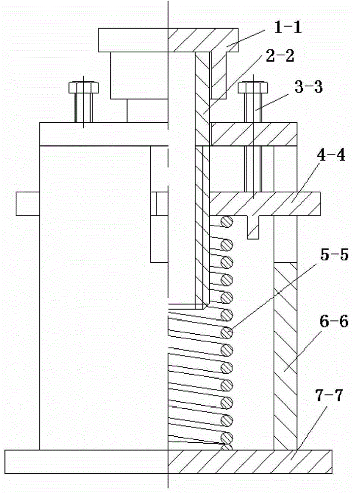
[0046] figure 2 As shown, an elastic compensation device of the present invention has a top plate 1-1, a pressure plate 4-4, an elastic shock absorbing part 5-5, a bottom plate 7-7, a shell 6-6, a load column 2-2 and several setting bolts 3 -3. The load column 2-2, the pressure plate 4-4 and the elastic shock absorbing part 5-5 are arranged in the shell 6-6, and the shell 6-6 is firmly connected with the bottom plate 7-7; the elastic shock absorbing part 5-5 is located on the bottom plate 7- Between the upper end surface of 7 and the lower end surface of the pressure plate 4-4, the elastic action end surface is respectively in contact with the upper end surface of the bottom plate 7-7 and the lower end surface of the pressure plate 4-4; 2-2 is fastened to the pressing plate 4-4; the top plate 1-1 is fastened to the load column 2-2.

Embodiment 2

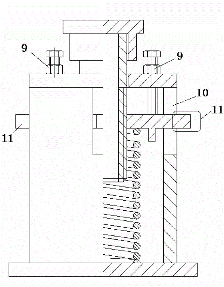
[0048] image 3 shown in figure 2 On the basis of the scheme shown, a lock nut 9 is added to further enhance the locking effect. Among them, the schematic diagram of the fastening connection between the load column 2-2 and the pressure plate 4-4 is as follows Figure 4 As shown, the fastening method selected in the figure is threaded connection. In this embodiment, the middle of the pressing plate 4-4 is provided with a threaded through hole that matches the external thread of the load column 2-2; the edge is provided with a guide and limit protrusion 10 that matches the outer shell 6-6 (the outer shell 6-2). 6 is correspondingly provided with the guide limit chute 11 that is matched with it, the guide limit protrusion 10 and the guide limit chute 11 jointly form the guide limit device that limits the movable space of the pressing plate 4-4), the specific structure is as Figure 5shown.

Embodiment 3

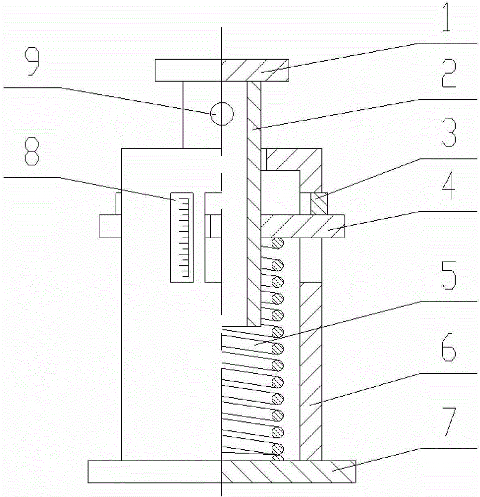
[0050] Figure 6 shown in image 3 On the basis of the scheme shown, a scale indicating part 8-8 is added to provide a numerical indication of the load borne by the top plate, to quantify the predetermined load to the displacement distance of the pressure plate 4-4, and to accurately control the elastic deformation error after precompression Within the allowable error range of the predetermined load.


PUM


Abstract

The invention relates to the technical field of elastic compensation devices, in particular to an elastic compensation device / group / bracket and an absorption tower device. The elastic compensation device solves the technical problem that an elastic compensation device of the prior art is inconvenient to relieve elastic pre-load in the use process; the elastic compensation device group solves the technical problems that the single elastic compensation device is low in bearing ability, and a plurality of single elastic compensation devices cannot be jointly arranged along a special direction; the elastic compensation bracket realizes the elastic vibration absorption of tower body support of a tower type structure and adapts to lateral deformation, and the absorption tower device solves and relieves the vibration of an absorption tower caused by the expansion of the tower body in the vertical direction under a high temperature working condition and balances the lateral displacement caused by the lateral expansion of the absorption tower.

Description

technical field [0001] The invention relates to the technical field of elastic compensation devices, in particular to an elastic compensation device / group / bracket and a resolution tower device. Background technique [0002] In industrial production, vertical heat exchangers, analytical towers, absorption towers, distillation towers and other tower equipment working under high temperature and high pressure will undergo shape changes such as expansion or contraction under the action of temperature and pressure. As a result, this type of equipment generates additional force at the fixing point, and these additional forces will cause greater harm to the equipment body. The method to solve this hazard in the prior art is to use elastic compensating devices such as: spring brackets, air springs and the like. [0003] In the prior art, when installing and using the elastic compensation device, it is necessary to apply a certain elastic preload to the device in advance, and use cor...

Claims


Application Information

Patent Timeline
Patent Type & Authority Applications(China)
IPC IPC(8): F16F7/00F16F9/02F16F9/10
CPCF16F7/00F16F9/02F16F9/10
Inventor 傅旭明肖中元
Owner ZHONGYE-CHANGTIAN INT ENG CO LTD
Why Eureka
Try Eureka