Output gear, production method of output gear and output gear device sub-assembly with output gear

A technology of output gears and sub-assemblies, applied in hoisting devices, transmission parts, components with teeth, etc., can solve the problems of short service life, unstable output, poor motion stability, etc., and simplify the configuration of varieties and quantities. , assembly simplification, cost reduction effect

Active Publication Date: 2015-04-29
KEIPER (CHANGSHU) SEATING MECHANISMS CO LTD
View PDF6 Cites 3 Cited by
  • Summary
  • Abstract
  • Description
  • Claims
  • Application Information

AI Technical Summary

Problems solved by technology

[0007] In addition, the existing output gear sub-assembly adopts a non-modular design for the output gear tooth shape requirements of different customers, and there are many assembly processes and a large number of parts
Furthermore, in the existing output gear sub-assembly, the supporting frame, the open bushing and the output gear key adopt clearance fit or transition fit, and the output is unstable.
In addition, the existing output gear sub-assembly adopts oil-free lubrication between the plastic bush and the support frame, which has poor motion stability, is easy to wear, and has a short service life.
Furthermore, the existing output gear sub-assembly relies on plastic bushings and supporting frames for radial positioning, and uses corrugated gaskets for axial positioning and eliminates gaps, which also results in a large number of parts and a large number of assembly processes.

Method used


Image

  • Output gear, production method of output gear and output gear device sub-assembly with output gear
  • Output gear, production method of output gear and output gear device sub-assembly with output gear
  • Output gear, production method of output gear and output gear device sub-assembly with output gear

Examples


Embodiment 1

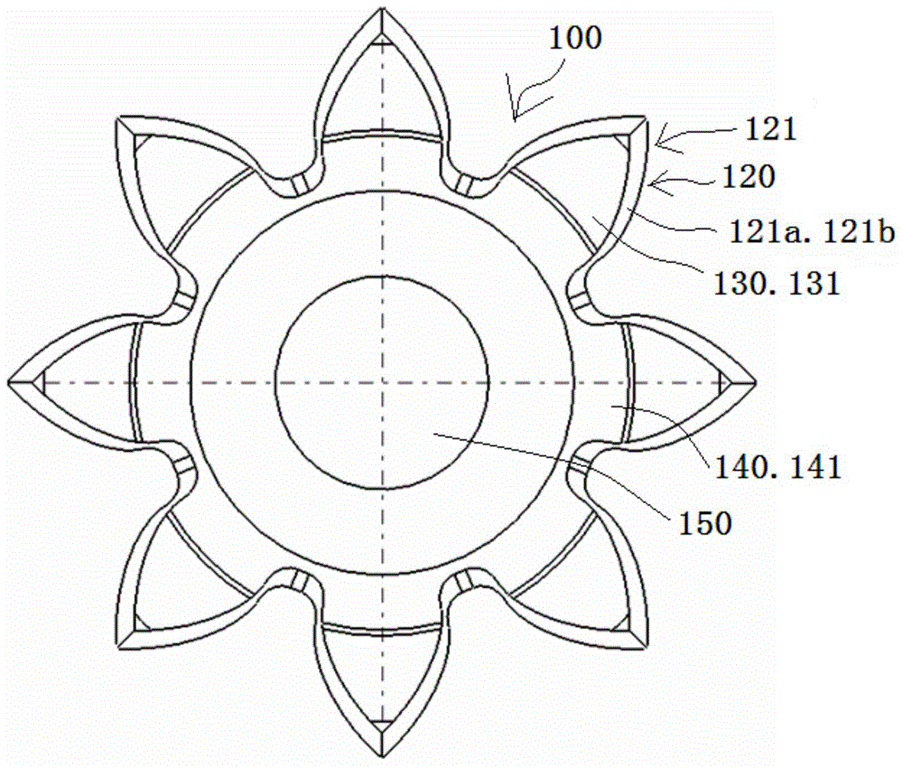
[0057] see Figure 3 to Figure 7 , the output gear 100 shown in the figure is divided into five concentric cylinders with different diameters, wherein the first cylinder 110 cooperates with the bearing to support the output gear 100, the front end of the second cylinder 120 and the first cylinder 110 The rear end is connected, and a plurality of second teeth 121 are arranged on the outer peripheral surface of the second section cylinder 120; Several third teeth 131 are matched with plum blossom holes in the plastic bushing, the front end of the fourth section cylinder 140 is connected with the rear end of the third section cylinder 130, and several first section teeth are also arranged on the outer peripheral surface of the fourth section cylinder 140. The four teeth 141 are interference fit with the tooth holes in the planetary gear transmission, and the end of the fifth column 150 is connected with the rear of the fourth column 140, and is matched with the round hole of the ...

Embodiment 2

[0062] see Figure 8 and Figure 9 , the output gear shown in the figure, the tooth top surface of the second segment tooth 121b is located on the same cylindrical surface. The diameter is equal to the outer diameter of the third tooth 131. All the other are with embodiment 1.

Embodiment 3

[0064] see Figure 10 and Figure 11 , the output gear shown in the figure, the tooth top surface of the second segment tooth 121b is located on the same conical surface, the front end of the conical surface is tangentially connected with the rear end of the first segment tooth 121a, and the rear end of the conical surface The end is connected tangentially to the tooth top surface of the third tooth 131. All the other are with embodiment 1.


PUM


Abstract

The invention discloses an output gear. The output gear comprises five concentric cylinders unequal in diameter. The outer periphery of the second concentric cylinder, the outer periphery of the third concentric cylinder and the outer periphery of the fourth concentric cylinder are provided with second teeth, teeth and fourth teeth, respectively; the second teeth, the third teeth and the fourth teeth are equal to one another in number of tooth; each second tooth comprises first tooth segment and a second tooth segment, the modulus from the front end of the second tooth segment to the rear end thereof is gradient, the front end modulus of the second tooth segment is equal to the modulus of the first tooth segment, the rear end modulus of the second tooth segment is equal to the modulus of the corresponding third tooth. The output gear has the advantages that the problem that output gear device sub-assembly of the existing market is unable to meet the different requirements of different customers for linking portion (between a tooth plate and the output gear) is solved, the requirements on both process and strength are met, and the problems such as the demand on high quantity of new parts and low modular degree are solved. The invention further discloses the production method of the output gear and the output gear device sub-assembly with the output gear.

Description

technical field [0001] The invention belongs to the car seat design technology, and particularly relates to an output gear structure of a car seat transmission mechanism and a preparation method thereof, and an output gear device subassembly using the output gear. The output gear used in the car seat transmission mechanism is its The output tooth structure with the same number of teeth and different modulus is used for meshing with the tooth plate and the planetary gear transmission, so as to ensure that the output gear can resist 200-300Nm torque in the direction of rotation and the edge thickness of the planetary gear transmission can be guaranteed to be greater than the requirement of 1 material thickness. Background technique [0002] The output tooth device sub-assembly of tooth plate and tooth structure applied to the car seat transmission mechanism in the existing market is like the output tooth device sub-assembly of the tooth plate and tooth structure disclosed in US...

Claims


Application Information

Patent Timeline
Patent Type & Authority Applications(China)
IPC IPC(8): F16H55/17F16H55/12F16H55/08F16H57/08B23P15/14
CPCB23P15/14F16H55/08F16H55/12F16H55/17F16H57/08
Inventor 庄伟清聂维钦黎其俊常健
Owner KEIPER (CHANGSHU) SEATING MECHANISMS CO LTD
Why Eureka
Try Eureka