Shaft sealing device

A shaft seal and hard seal technology, which is applied in the direction of engine seals, engine components, mechanical equipment, etc., can solve the problems of easy wear and seal failure of the seal ring 4, so as to avoid wear and aging, improve the sealing effect, and slow down aging effect

Inactive Publication Date: 2015-04-29
张云龙
View PDF1 Cites 2 Cited by
  • Summary
  • Abstract
  • Description
  • Claims
  • Application Information

AI Technical Summary

Problems solved by technology

[0004] In the above-mentioned shaft sealing device, by tightening the screw 6, the sealing ring 4 is deformed and tightly attached between the outside of the shaft 1 and the inner wall of the sealing ring seat 2. As the rotation time of the shaft 1 increases, the sealing ring 4 is prone to wear and tear, which makes the seal invalid

Method used


Image

  • Shaft sealing device
  • Shaft sealing device

Examples


Embodiment 1

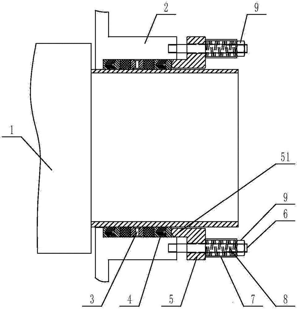
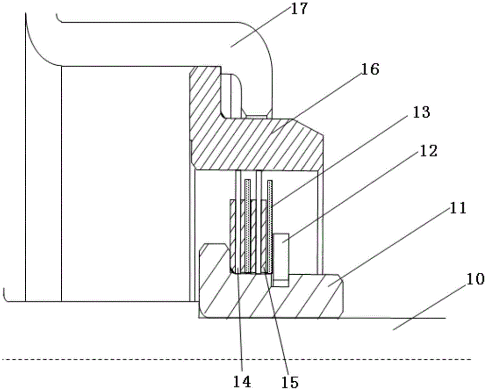
[0036] Embodiment 1, the shaft sealing device such as figure 2 As shown, it includes a rotating shaft 10, a labyrinth inner sleeve 11, a snap ring 12, a hard seal ring 13, a spacer ring 15, a soft seal ring 14, a labyrinth outer sleeve 16, and a seal ring seat 17;

[0037] The sealing ring seat 17 is pivotably sleeved on the rotating shaft 10;

[0038] The labyrinth jacket 16 is fixed on the sealing ring seat 17;

[0039] The labyrinth inner sleeve 11 is fixedly sleeved on the rotating shaft 10;

[0040] The labyrinth outer cover 16, the labyrinth inner cover 11, and the rotating shaft 10 are coaxial, and the labyrinth outer cover 16 is set outside the labyrinth inner cover 11;

[0041] The labyrinth inner sleeve 11 is provided with an annular groove in the middle;

[0042] The inner edge of the clasp 12 is embedded in the annular groove, and fixed on the outer edge of the middle part of the labyrinth inner sleeve 11;

[0043] The labyrinth inner sleeve 11 has a boss on t...

Embodiment 2

[0055] Based on the first embodiment, there may be one or more sets of hard sealing rings 13 , spacer rings 15 , soft sealing rings 14 and spacer rings 15 .

[0056] The more groups of hard seal ring 13, spacer ring 15, soft seal ring 14 and spacer ring 15, the better the sealing effect.

[0057] Preferably, there are two groups of hard seal rings 13, spacer rings 15, soft seal rings 14, and spacer rings 15. The ring, the soft sealing ring, and the spacer ring are sequentially sleeved and fixed on the outer edge of the labyrinth inner sleeve 11 between the snap ring 12 and the boss at the bottom outer edge of the labyrinth inner sleeve 11 . Two sets of hard sealing rings 13, spacer rings 15, soft sealing rings 14, and spacer rings 15 can not only achieve ideal sealing effects, but also effectively control costs.

Embodiment 3

[0059] Based on the first embodiment, the hard sealing ring 13 can be made of steel or other hard non-metallic materials;

[0060] The soft sealing ring 14 can be made of polytetrafluoroethylene, rubber or polycarbonate;

[0061] The spacer ring 15 can be made of steel or epoxy resin.


PUM


Abstract

The invention discloses a shaft sealing device. The shaft sealing device comprises a rotating shaft, a maze inner sleeve, a clamping ring, hard sealing rings, partition rings, soft sealing rings, a maze outer sleeve and a sealing ring base. An annular groove is formed in the middle of the maze inner sleeve. The inner edge of the clamping ring is embedded in the annular groove and fixed to the outer edge of the middle of the maze inner sleeve. A boss is arranged on the outer edge of the bottom of the maze inner sleeve. The hard sealing rings, the partition rings and the soft sealing rings are sequentially arranged and fixed between the clamping ring and the boss on the outer edge of the bottom of the maze inner sleeve in a sleeving mode. The clamping ring is pressed on a hard sealing piece. The hard sealing rings and the soft sealing rings are separated through the partition rings. The gap between the outer edges of the soft sealing rings and the inner edge of the maze outer sleeve is 0 or a first distance. The gap between the outer edges of the hard sealing rings and the inner edge of the maze outer sleeve is a second distance. The gap between the outer edges of the partition rings and the inner edge of the maze outer sleeve is a third distance. The first distance is smaller than the second distance which is smaller than the third distance. The shaft sealing device is resistant to aging and abrasion and good in sealing effect.

Description

technical field [0001] The invention relates to sealing technology, in particular to a shaft sealing structure. Background technique [0002] On the input and output shafts of the sealed chamber, in order to prevent air, dust, water, etc. from entering the sealed chamber, shaft sealing devices are usually provided. The structure of the shaft sealing device disclosed in Chinese patent application 201110155620.9 is as follows figure 1 As shown, it includes a sealing ring seat 2 sleeved on the outside of the shaft 1, an annular cavity 3 is formed between the sealing ring seat 2 and the shaft 1, and a sealing ring 4 is sleeved on the shaft 1, and the sealing ring 4 is located in the cavity 3, one side of the sealing ring seat 2 is provided with a sealing material flange 5, and the sealing material flange 5 is set outside the shaft 1, and the side of the sealing material flange 5 close to the sealing ring seat 2 is provided with an annular boss 5l , the annular boss 5l is match...

Claims


Application Information

Patent Timeline
Patent Type & Authority Applications(China)
IPC IPC(8): F16J15/16F16J15/447
CPCF16J15/16F16J15/447
Inventor 张云龙
Owner 张云龙
Why Eureka
Try Eureka