Gas turbine combustor transition section with cooling structure

A technology of gas turbine and cooling structure, which is applied in combustion chamber, continuous combustion chamber, combustion method, etc., can solve the problems of thermal barrier coating peeling off easily, temperature rise in transition section, thermal barrier coating damage, etc. Thermal effect, low pressure loss, effect of reducing metal temperature

Inactive Publication Date: 2015-04-29
BEIJING HUAQING GAS TURBINE & INTEGRATED GASIFICATION COMBINED CYCLE ENG TECH
View PDF7 Cites 1 Cited by
  • Summary
  • Abstract
  • Description
  • Claims
  • Application Information

AI Technical Summary

Problems solved by technology

Since the inner surface of the transition section needs to be sprayed with a thermal barrier coating, the process of developing cooling holes will cause a certain degree of damage to the thermal barrier coating
After the therm

Method used


Image

  • Gas turbine combustor transition section with cooling structure
  • Gas turbine combustor transition section with cooling structure
  • Gas turbine combustor transition section with cooling structure

Examples


Embodiment Construction

[0016] The specific implementation manners of the present invention will be further described in detail below in conjunction with the accompanying drawings and embodiments. The following examples are used to illustrate the present invention, but are not intended to limit the scope of the present invention.

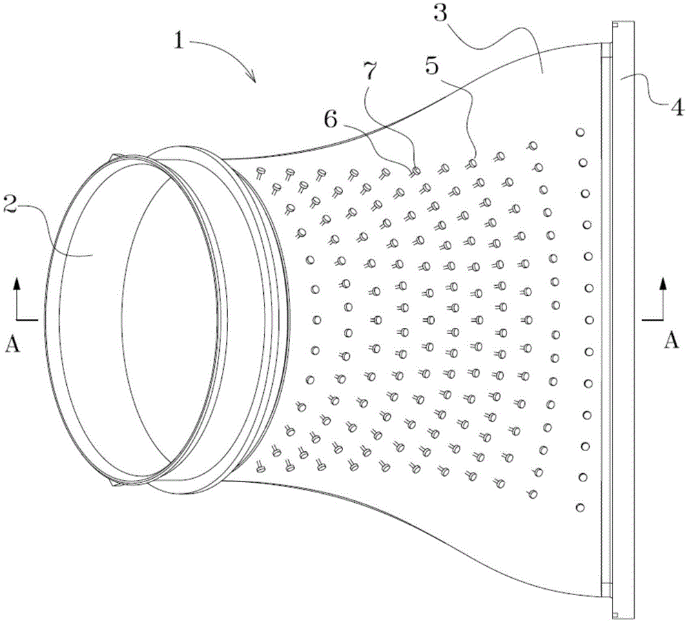
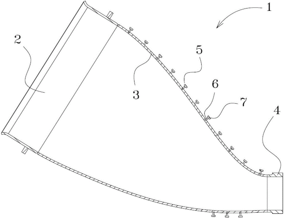
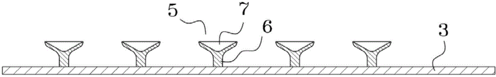
[0017] Such as figure 1 and figure 2 As shown, the transition section 1 includes a transition section inlet 2, a transition section body 3 and a transition section outlet 4. High-temperature gas enters the transition section through the transition section inlet 2, flows inside the transition section body 3, and gradually transitions from a circular cross section As far as the fan-shaped section is concerned, the outlet 4 of the transition section is also fan-shaped, and a plurality of transition sections 1 are arranged in a circle around the axis of the gas turbine. There are a plurality of cooling components 5 on the transition section body 3, each of the cooling compo...


PUM


Abstract

The invention discloses a gas turbine combustor transition section with a cooling structure, and belongs to the technical field of a gas turbine. The outer surface of a transition section body is provided with a plurality of cooling components; each cooling component comprises a connecting piece and a heat dissipation part; the cooling components are distributed in an array, and every two adjacent cooling members are distributed in a staggered manner; each heat dissipation part is in the shape of a bowl or is spiral or dendritic or is in other shapes that not only can surface area be increased but also flow resistance is smaller. According to the gas turbine combustor transition section disclosed by the invention, the temperature of the transition section can be lowered and the service life of the transition section can be prolonged by increasing the heat exchange area of the outer surface of the transition section; meanwhile, the integrity of the transition section body cannot be broken, the reliability of a thermal barrier coating cannot be influenced and the thermal insulation effect of the can be helped to be enhanced by the cooling structure; pressure loss brought by the cooling structure is low, so that the efficiency of the gas turbine can be helped to be improved.

Description

technical field [0001] The invention relates to the technical field of gas turbines, in particular to a transition section of a combustion chamber of a gas turbine with a cooling structure. Background technique [0002] Heavy-duty gas turbines usually use several cylindrical combustors to generate hot gas that is introduced into the first stage turbine vanes of the engine. The first stage turbine vane accepts preferably annular hot gas. Through a transition section, placed between each combustion chamber and the first-stage turbine vane, the gas flow field ejected from each combustion chamber is changed from a roughly cylindrical shape to a part of a ring. Therefore, the air flow ejected from all the transition sections produces an ideal annular air flow. [0003] The thermodynamic efficiency possible for a heat engine depends on the maximum temperature of its working fluid and, in the case of a gas turbine, on the hot gas exhausted from the combustion chamber. The maximu...

Claims


Application Information

Patent Timeline
IPC IPC(8): F23R3/00
Inventor 刘小龙吕煊张珊珊
Owner BEIJING HUAQING GAS TURBINE & INTEGRATED GASIFICATION COMBINED CYCLE ENG TECH
Why Eureka
Try Eureka