Component height difference detecting device

A detection equipment and height difference technology, which is applied in the field of parts height difference detection equipment, can solve the problems of whether the placement is correct or not, the part number of the carrier cannot be determined, and the quality of the parts is affected, so as to improve supply efficiency, improve operation efficiency, Ease of use

Active Publication Date: 2015-04-29
BOZHON PRECISION IND TECH CO LTD
View PDF6 Cites 19 Cited by
  • Summary
  • Abstract
  • Description
  • Claims
  • Application Information

AI Technical Summary

Problems solved by technology

[0002] In the production or assembly workshop, etc., sometimes it is necessary to detect the height difference between the part and the reference on the carrier, so as to facilitate the next operation of the part, and the part needs to be installed on the carrier, and the carrier usually transports the parts through the assembly line , while the assembly line mechanism in the prior art only drives the conveyor belt forward by the driving device, and the carrier moves forward under the action of the conveyor belt. During the forward movement, whether there is a carrier on the assembly line cannot be detected. It cannot be determined, and it is impossible to detect whether the position of the parts is correct. Sometimes the carrier needs to be separated from the conveyor belt before the parts can be installed on the carrier. When the parts need to be operated, the carrier needs to be stationary, but the existing technology The assembly line cannot realize the above functions, resulting in unexpected situations during the detection process of the parts, which not only affects the work efficiency, but also affects the quality of the parts

Method used


Image

  • Component height difference detecting device
  • Component height difference detecting device
  • Component height difference detecting device

Examples


Embodiment Construction

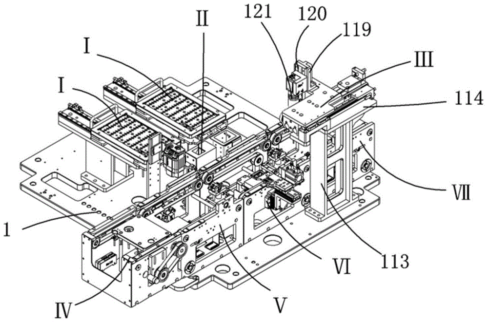
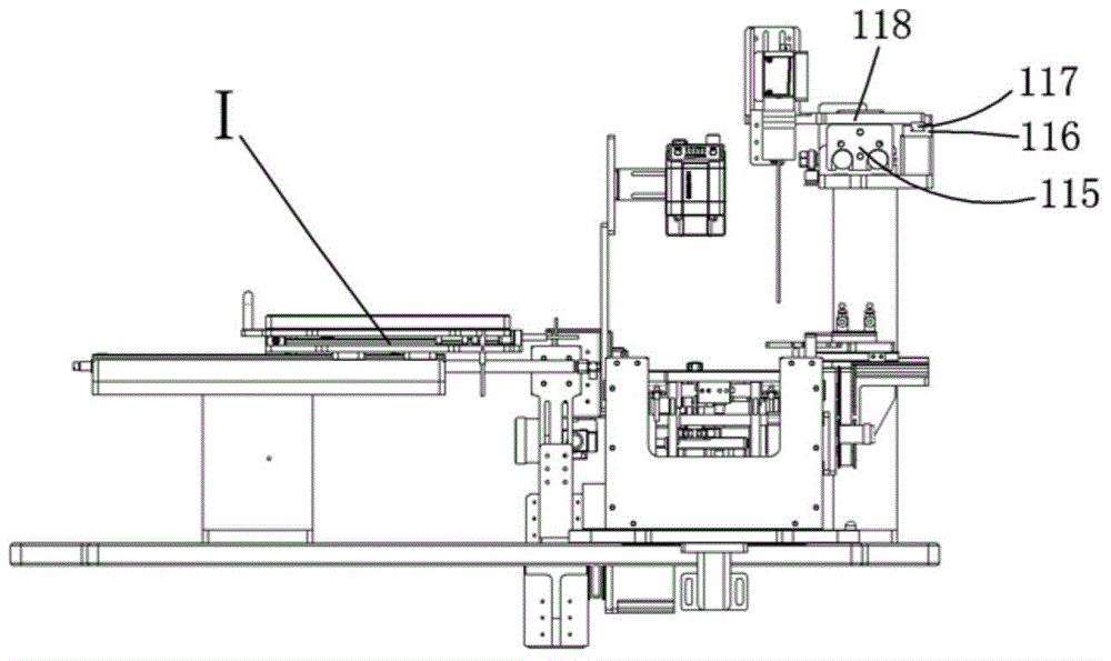
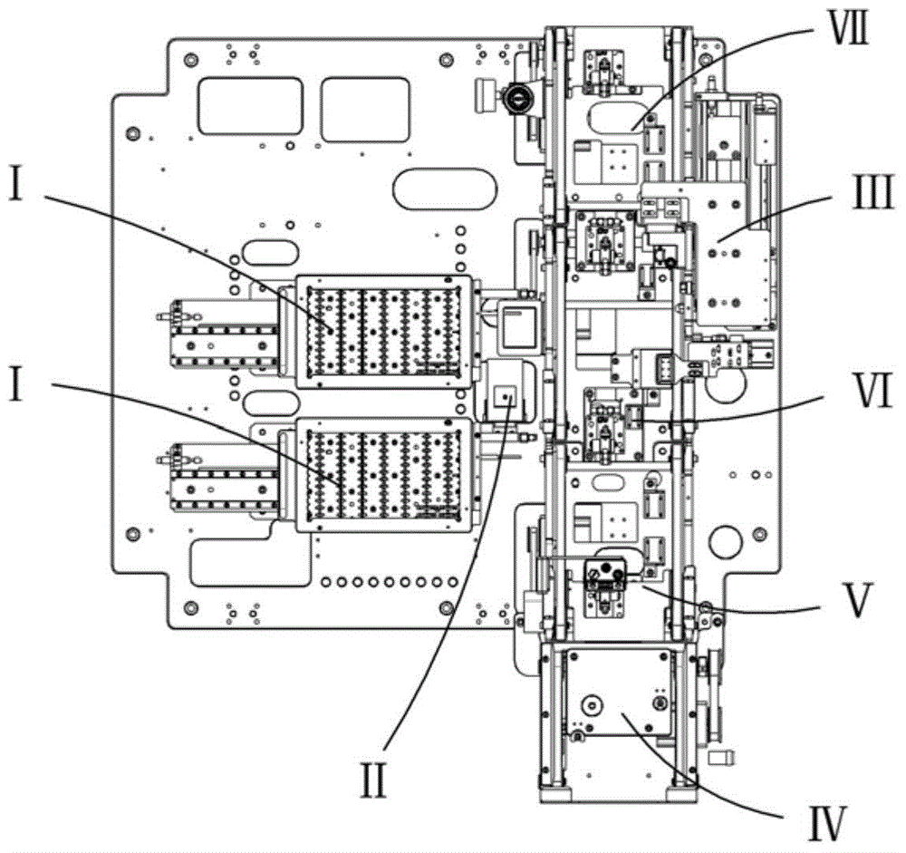
[0045] Examples, see attached Figure 1-20 , a component height difference detection device, which includes a bottom plate 1, a tray mechanism I, an assembly line mechanism, a CCD mechanism II and a detection alignment mechanism III, two sets of tray mechanisms are installed on the rear of the bottom plate, and two sets of tray mechanisms are installed on the front of the bottom plate An assembly line mechanism is installed, a detection alignment mechanism is installed on the right front side of the bottom plate, and a CCD mechanism is installed on the bottom plate between the two groups of tray mechanisms and the assembly line mechanism.

[0046] The tray mechanism is a mechanism with automatic and manual two-stage feeding. It includes a tray bottom plate 2, a tray support plate 3, a panel 4 and a tray 5. Two groups of materials are installed on the tray bottom plate. The disc support plate, two groups of tray support plates are equipped with a panel, the panel is equipped wi...


PUM


Abstract

The invention relates to a component height difference detecting device. Material is fed in a material feeding assembly line mechanism, and a first assembly line mechanism is capable of blocking a carrier and scanning a serial number of a component through a bar-code scanner; the component is driven by a manipulator to move to the position of a CCD mechanism and to take a picture, and the component position is calibrated; a second assembly line mechanism is capable of separating the carrier from a conveyer belt and blocking the forward movement of the carrier, and the carrier is capable of maintaining level after the carrier is lifted up; the component is placed on the carrier through the manipulator, a material pressing mechanism is driven by a driving air cylinder and a lifting air cylinder to drive a material pressing plate to press the component after the component is placed, a detecting counterpoint mechanism is driven by the manipulator and is transported to the position above the component, a height difference between the component and the datum on the carrier is detected, and after the height difference is detected, the material pressing mechanism is moved out, a mandril is retreated, and the carrier is continuously transported forward to a material discharging assembly line mechanism for material discharging. The component height difference detecting device is used for detecting the height difference on small components of electronic products, the height difference can be confirmed, and the next step of operation is prepared.

Description

Technical field: [0001] The invention relates to the field of detection equipment, in particular to a detection equipment for height difference of parts. Background technique: [0002] In the production or assembly workshop, etc., sometimes it is necessary to detect the height difference between the part and the reference on the carrier, so as to facilitate the next operation of the part, and the part needs to be installed on the carrier, and the carrier usually transports the parts through the assembly line , while the assembly line mechanism in the prior art only drives the conveyor belt forward by the driving device, and the carrier moves forward under the action of the conveyor belt. During the forward movement, whether there is a carrier on the assembly line cannot be detected. It cannot be determined, and it is impossible to detect whether the position of the parts is correct. Sometimes the carrier needs to be separated from the conveyor belt before the parts can be in...

Claims


Application Information

Patent Timeline
Patent Type & Authority Applications(China)
IPC IPC(8): G01B11/02
Inventor 吕绍林汪炉生代飞李忠张泽庞
Owner BOZHON PRECISION IND TECH CO LTD
Why Eureka
Try Eureka