
Laser vision profile measurement system, measurement method and three-dimensional target

A profile measurement and target technology, which is applied to measurement devices, optical devices, instruments, etc., can solve problems such as calibrating complex measurement coordinate systems, and achieve good technical advantages and simple operation.

Inactive Publication Date: 2015-04-29
TIANJIN UNIV
View PDF4 Cites 34 Cited by
  • Summary
  • Abstract
  • Description
  • Claims
  • Application Information

AI Technical Summary

Problems solved by technology

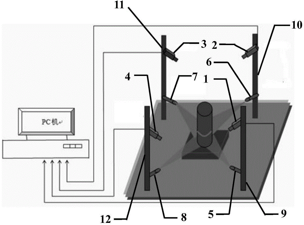
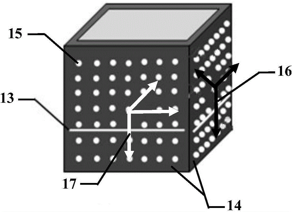
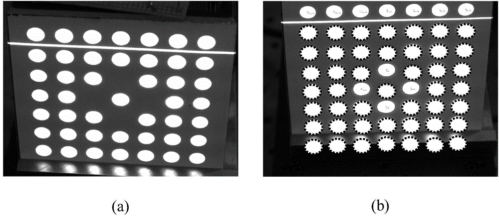
[0004] In order to overcome the above-mentioned prior art, the present invention proposes a laser vision contour measurement system and its rapid calibration method and three-dimensional target. Orientation measurement; at the same time, in order to solve the problem of calibration complexity and measurement coordinate system caused by the introduction of multiple sensors, this program also designed a new LED three-dimensional target based on the calibration process of the Zhang camera, and according to the target characteristics, design A global unified calibration method for profile sensors is proposed; and a laser vision profile measurement system is proposed, which uses LED stereo targets to achieve rapid calibration first, and then realizes the accurate measurement method of the three-dimensional profile of the measured object

Method used


Image

  • Laser vision profile measurement system, measurement method and three-dimensional target
  • Laser vision profile measurement system, measurement method and three-dimensional target
  • Laser vision profile measurement system, measurement method and three-dimensional target

Examples


Embodiment Construction

[0022] The present invention will be described in detail below in conjunction with the accompanying drawings and specific embodiments, but the implementation scope of the present invention is not limited thereto.

[0023] In order to solve the problem that a single set of visual sensor has a limited field of view and cannot measure the surface profile of the measured object in an all-round way, the present invention proposes a set of laser visual profile measurement system, combined with the Zhang camera calibration process, and designed a new type of LED three-dimensional target, And according to the characteristics of the target, a fast and unified calibration method that can be applied to industrial sites is designed.

[0024] 1. Laser Vision Contour Measurement System

[0025] Such as figure 1 Shown is a structural diagram of the laser vision contour measurement system of the present invention.

[0026] The system includes four linear lasers, four CCD cameras and other m...


PUM


Abstract

The invention discloses a laser vision profile measurement system, a measurement method and a three-dimensional target. The system comprises a measurement part and a calibration part, wherein the measurement part comprises four line lasers and four CCD (charge coupled device) cameras, and each laser and each CCD camera form a sensor; the calibration part comprises one three-dimensional target adopting a hollow cube structure. The specific measurement method comprises the following steps: calibration of the measurement system and coordinate unification are realized through the three-dimensional target firstly, and then the three-dimensional profile of a measured object is measured. By means of the LED three-dimensional target, all that is required is to place the target in multiple positions freely in a field range of the cameras in a calibration process, the operation is simple, overall unified calibration of the sensors can be finished rapidly and conveniently, and application to the industrial field can be realized; and the scheme has better technical advantages for occasions where the section profile of an object is required to be measured comprehensively such as on-line measurement of the section profile size of various mechanical parts.

Description

technical field [0001] The invention relates to a structured light three-dimensional vision inspection technology, in particular to a rapid calibration method for a laser vision contour measurement system and a three-dimensional target. Background technique [0002] Structured light three-dimensional visual measurement technology has the advantages of non-contact visual measurement, high speed, high degree of automation, and good flexibility. Structured light 3D vision is based on the principle of optical triangulation, and calculates the surface profile of the measured object by calculating the offset information of various light mode feature points in the collected image. The optical projector projects a certain light pattern, which makes the structured light image information easy to extract, so the measurement accuracy is high, and it is widely used in the online detection of various industrial products. [0003] A typical line structured light vision sensor consists of...

Claims


Application Information

Patent Timeline
IPC IPC(8): G01B11/25
Inventor 马旭王鹏孙长库王中亚
Owner TIANJIN UNIV
Learn More