Rock abrasiveness determination method

A measurement method and abrasive technology, applied in the direction of testing wear resistance, etc., can solve the problems of discrepancy, little guidance on the selection and use of drill bits, and no drilling depth.

Inactive Publication Date: 2015-04-29
CHINA PETROCHEMICAL CORP +1
View PDF5 Cites 13 Cited by
  • Summary
  • Abstract
  • Description
  • Claims
  • Application Information

AI Technical Summary

Problems solved by technology

However, there is a common problem in these methods. The experimental measurement method does not match the actual drilling conditions. There is no drilling depth, only the surface is worn, and the friction and wear of the cuttings on the drill bit cannot be reflected. There are limitations. The selection and use of the drill bit little guidance

Method used


Image

  • Rock abrasiveness determination method
  • Rock abrasiveness determination method

Examples


Embodiment 1

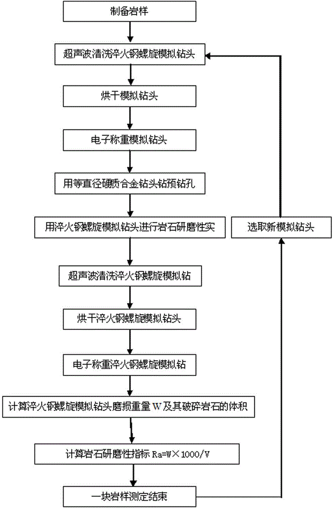
[0025] A rock abrasiveness determination method, comprising the following steps:

[0026] (1) Preparation of standard rock samples;

[0027] (2) Cleaning, drying and weighing of the hardened steel helical simulation drill bit before the experiment;

[0028] (3) Drill pre-drilled holes;

[0029] (4) Determination of rock abrasiveness;

[0030] (5) Cleaning, drying and weighing after the test of the hardened steel helical simulation drill bit;

[0031] (6) Calculation of rock abrasiveness index.

Embodiment 2

[0033] Embodiment 2 is a further refinement of Embodiment 1. Among them: the rock sample described in step (1) needs to be parallel to the upper and lower ends, the diameter is greater than the cylindrical shape of the hardened steel helical simulation drill bit, and the height is 150-200mm; A cemented carbide drill bit with the same diameter as the simulated micro drill bit drills a hole with a depth of 10-20mm; the rock abrasiveness measurement parameters described in step (4) are the rotational speed 200 r / min, the drill pressure 500N, and record the drilled depth during the experiment; Before and after the simulated drill bit experiment described in steps (2 and 5), it needs to be cleaned and dried with an ultrasonic cleaner, and weighed with an electronic balance; the abrasiveness index R of the rock described in step (6) a It is the ratio of the wear weight W (mg) of the quenched steel helical simulated micro-drill bit to the wear volume V (mm3) of the broken rock before...

Embodiment 3

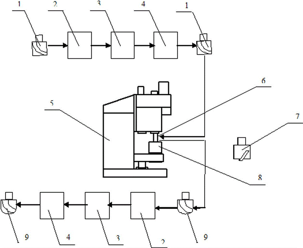
[0035] Refer to attached figure 1 and figure 2 , including the following steps:

[0036] (1) Preparation of standard rock sample 8;

[0037] (2) Wash, dry and weigh the quenched steel helical simulation drill bit 1 before the experiment;

[0038] (3) Install the cemented carbide drill bit 7 of equal diameter on the drill rod 6 to drill a 20mm pre-drilled hole;

[0039] (4) Remove the drill bit 7, and install the weighed quenched steel helical simulation drill bit 1 on the drill pipe 6 for rock abrasiveness experiments. After the experiment, record the drilling depth;

[0040] (5) Remove the hardened steel helical simulation drill bit 1 for cleaning, drying and weighing;

[0041] (6) Calculate the wear weight W of the hardened steel helical simulation drill bit 1 and the volume V of the broken rock sample 8 to obtain the abrasiveness Ra of the rock.

[0042] Further, described rock abrasiveness measuring method, in order to better simulate the actual drilling conditions, ...


PUM

PropertyMeasurementUnit
heightaaaaaaaaaa
diameteraaaaaaaaaa
heightaaaaaaaaaa

Abstract

The invention relates to a rock abrasiveness determination method in the field of a rock abrasiveness experiment determination method in petroleum engineering industry. The rock abrasiveness determination method comprises the following steps: preparing a standard rock sample; washing, drying and weighing a quenched steel helix simulation drill bit before experiment; drilling a prebored hole; determining the rock abrasiveness; washing, drying and weighing after the quenched steel helix simulation drill bit after experiment; and calculating the rock abrasiveness index. The rock abrasiveness determination method truly shows the abrasiveness characteristics of rocks to rock breaking tools during drilling process: I. the frictional wear of the rock to the drilling bit in rock breaking; II. The frictional wear of generated rock chips to the drilling bit. The invention provides a new method for reasonably evaluating the rock abrasiveness for the technical field of petroleum engineering.

Description

technical field [0001] The invention relates to the field of rock abrasiveness test methods in the petroleum engineering industry, in particular to a rock abrasiveness test method for rocks with a hardened steel helical simulation drill bit under given indoor conditions. Background technique [0002] The abrasiveness of the rock is the ability of the rock to wear the rock-breaking tool when the rock-breaking tool (drill bit) rubs against the rock. Practice has proved that the same type of drill bit has a long life, more footage, and faster drilling speed in low abrasive formations, but its use effect is not satisfactory in high abrasive and hard formations, which shows that the drill bit has a certain impact on the drilled ground. The nature of the formation is very sensitive. At present, there are many methods for determining the abrasiveness of rocks at home and abroad. The experimental materials include cores, cuttings, rock blocks, etc., and the grinding tools include c...

Claims


Application Information

Patent Timeline
Patent Type & Authority Applications(China)
IPC IPC(8): G01N3/56
Inventor 赵秀菊魏振燕静郭淑玲程鹏吴明波
Owner CHINA PETROCHEMICAL CORP
Why Eureka
Try Eureka