
Optical excitation and ultrasonic excitation combined infrared nondestructive testing device

A technology of infrared non-destructive testing and composite excitation, which is applied in the direction of optical testing for flaws/defects, etc. It can solve problems such as short excitation energy and excitation time, failure to detect internal damage, and limited detectable depth, so as to improve detection accuracy and sensitivity. , Make up for the lack of detection ability, reduce the effect of false detection and missed detection

Active Publication Date: 2015-04-29
GUOBIAO BEIJING TESTING & CERTIFICATION CO LTD
View PDF6 Cites 8 Cited by
  • Summary
  • Abstract
  • Description
  • Claims
  • Application Information

AI Technical Summary

Problems solved by technology

However, there are also some shortcomings. In the pulsed flash thermal excitation mode, the excitation energy and excitation time are short, the detectable depth is limited, and deep internal damage cannot be found; the shape of the specimen is high, which is not conducive to the detection of thicker and test pieces with complex shapes, etc.

Method used

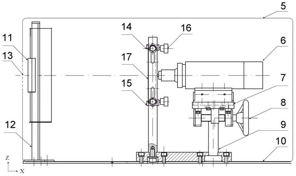
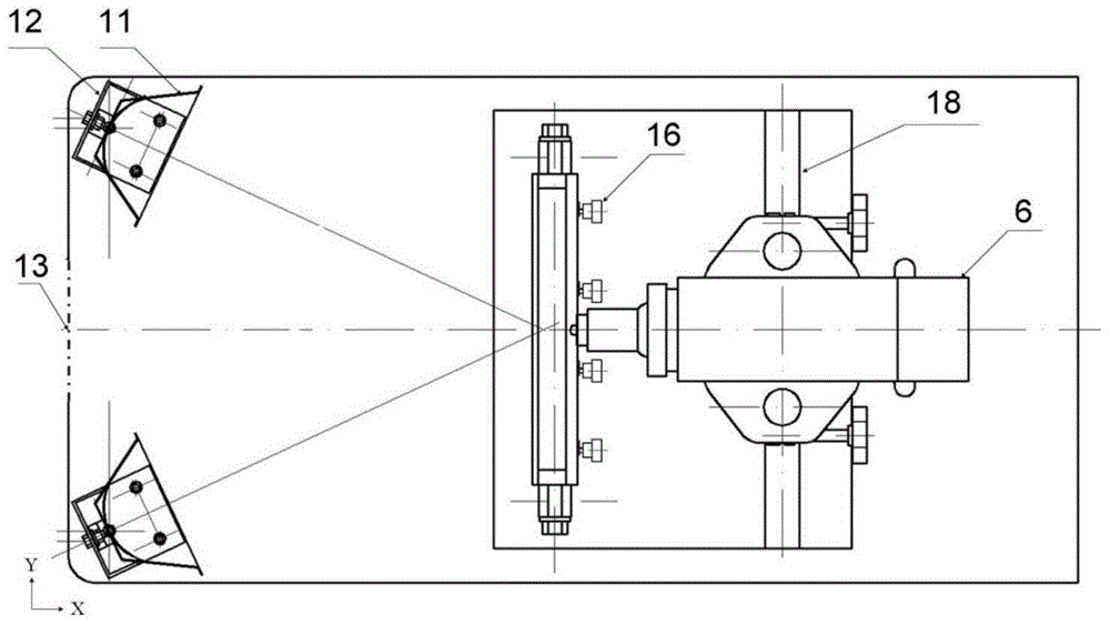

Image

  • Optical excitation and ultrasonic excitation combined infrared nondestructive testing device
  • Optical excitation and ultrasonic excitation combined infrared nondestructive testing device
  • Optical excitation and ultrasonic excitation combined infrared nondestructive testing device

Examples


Embodiment Construction

[0026] The preferred embodiments are described in detail below in conjunction with the drawings. It should be emphasized that the following description is only exemplary, and is not intended to limit the scope and application of the present invention.

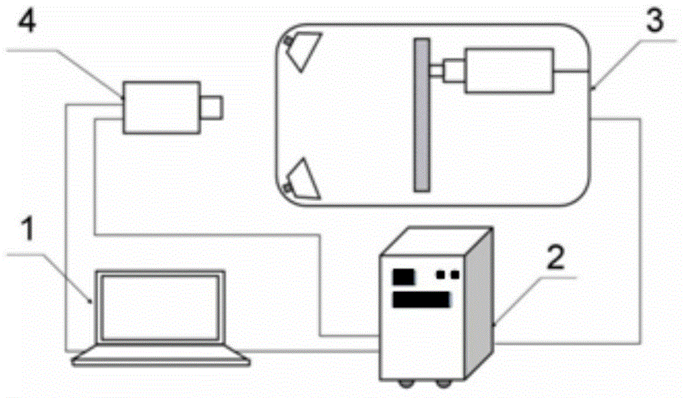
[0027] figure 1 It is a schematic diagram of the structure of the infrared thermal wave nondestructive testing system provided by the present invention. figure 1 Among them, the infrared non-destructive testing device provided by the present invention is composed of a computer 1, a control cabinet 2, an excitation system 3 and an infrared thermal imager 4. The computer 1 is connected to the infrared thermal imager 4 through the IEEE1394 interface to collect and process infrared thermal images; it is connected to the control cabinet 2 through the RS232 communication line to control the test process. The control cabinet 2 is connected to the infrared thermal imager 4 through a trigger circuit to perform a synchronous external trigge...


PUM


Abstract

The invention discloses an optical excitation and ultrasonic excitation combined infrared nondestructive testing device. The device comprises a computer, a control cabinet, an excitation system and an infrared thermal imager, wherein the computer is connected with the infrared thermal imager and the control cabinet respectively; the computer is used for controlling the testing process and analyzing the testing result; the control cabinet is connected with the computer, the excitation system and the infrared thermal imager respectively; the control cabinet is used for controlling signal conversion and providing a power supply required by the excitation system; the excitation system is used for applying optical excitation and ultrasonic excitation to a tested sample; the infrared thermal imager is used for recording the temperature field change of a tested surface. In combination of the testing result obtained in different excitation manners, the defect testing accuracy and sensitivity are improved, the defect of poor detectability in a single excitation mode is overcome, false testing and missing testing are reduced, and the infrared nondestructive testing application range is enlarged.

Description

Technical field [0001] The invention belongs to the field of non-destructive testing, and in particular relates to an infrared non-destructive testing device excited by light and ultrasound. Background technique [0002] Infrared thermal wave non-destructive testing technology is an emerging non-destructive testing technology developed at the end of the last century. It applies thermal wave excitation to the test piece, and the test piece absorbs the excitation energy and conducts it into the test piece. When the test piece has defects, Due to the different thermal characteristics of the defect location and the material of the test piece, the distribution of the temperature field on the surface of the test piece is abnormal. The infrared thermal imaging system is used to identify and analyze the abnormal temperature field to achieve the purpose of detecting defects. Compared with conventional non-destructive testing methods, it is very suitable for detecting and monitoring the de...

Claims


Application Information

Patent Timeline
Patent Type & Authority Applications(China)
IPC IPC(8): G01N21/88
Inventor 李璞朱其芳马通达张东晖张红菊王福生
Owner GUOBIAO BEIJING TESTING & CERTIFICATION CO LTD
Learn More