Double-power-supply voltage detection circuit

A technology of voltage detection circuit and dual power supply, which is applied in the direction of measuring current/voltage, measuring device, measuring electrical variables, etc., can solve the problems of increasing nonlinear error, nonlinear error affecting measurement and protection accuracy, and reducing reliability. Achieve the effects of resisting temperature drift, facilitating user wiring, and reducing process errors

Inactive Publication Date: 2015-04-29
CNC ELECTRIC GRP
View PDF4 Cites 1 Cited by
  • Summary
  • Abstract
  • Description
  • Claims
  • Application Information

AI Technical Summary

Problems solved by technology

[0002] In the traditional dual-supply voltage detection circuit with optocoupler as the core, there is only one optocoupler, which is like a general semiconductor device. Due to the change of ambient temperature, the transmitted signal will have temperature drift and certain nonlinear errors during use. Affect the measurement and protection accuracy, resulting in large errors in voltage measurement
Commonly used solutions use temperature compensation or operational amplifiers to achieve nonlinear correction, but the general temperature compensation accuracy is poor, and some increase the nonlinear error; and the use of operational amplifiers cannot solve the temperature drift of the optocoupler; If both compensation methods are adopted, not only the circuit design is complicated, but also the cost will be increased and the reliability will be reduced.
In addition, the common and standby power sources of the existing dual power supply voltage detection circuit need to be connected to respective power sources A, B, C, and N, and the neutral wire N cannot be lacked.

Method used


Image

  • Double-power-supply voltage detection circuit
  • Double-power-supply voltage detection circuit
  • Double-power-supply voltage detection circuit

Examples


Embodiment Construction

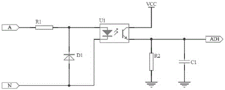
[0011] see figure 1 , which is a schematic diagram of a dual-supply voltage detection circuit with a traditional optocoupler as the core. Such as figure 1 As shown, there is only one optocoupler, which is like a general semiconductor device. Due to the change of ambient temperature, the transmitted signal will have temperature drift and certain nonlinear errors during use, which will affect the accuracy of measurement and protection, resulting in large voltage measurement. error.

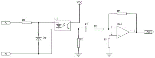
[0012] see figure 2 , which is a schematic diagram of a dual power supply voltage detection circuit with a traditional optocoupler as the core and an operational amplifier. Non-linear correction is achieved by using temperature compensation or the cooperation of operational amplifiers, but the general temperature compensation accuracy is poor, and some increase the nonlinear error; and the use of operational amplifiers cannot solve the temperature drift of the optocoupler.

[0013] Please refer...


PUM


Abstract

The invention relates to a double-power-supply voltage detection circuit. The double-power-supply voltage detection circuit comprises power supply input and further comprises voltage decreasing resistors R1, R2 and R3, an adjustable resistor RV1, amplitude limiting protection diodes D1 and D2, resistors R4, R5, R6 and R7, photoelectric couplers U1a, U1b, U2a and U2b and capacitors CD1 and CD2. The resistors R4 and R6 and the photoelectric coupler U1b form a feedback circuit, and the resistors R5 and R7 and the photoelectric coupler U2b form another feedback circuit. The double-power-supply voltage detection circuit effectively solves the problem that because the photoelectric couplers are affected by environment temperature, temperature excursion occurs, the linearity degree of the photoelectric couplers is greatly increased, and the requirement for accurately measuring a voltage signal of the double-power-supply product is met better; technology errors generated in the production process are reduced for the photoelectric couplers, and assembling and wiring of a user are facilitated.

Description

technical field [0001] The invention relates to the technical field of voltage detection, and more specifically, to a dual power supply voltage detection circuit. Background technique [0002] In the traditional dual-supply voltage detection circuit with optocoupler as the core, there is only one optocoupler, which is like a general semiconductor device. Due to the change of ambient temperature, the transmitted signal will have temperature drift and certain nonlinear errors during use. Affect the measurement and protection accuracy, resulting in large errors in voltage measurement. Commonly used solutions use temperature compensation or operational amplifiers to achieve nonlinear correction, but the general temperature compensation accuracy is poor, and some increase the nonlinear error; and the use of operational amplifiers cannot solve the temperature drift of the optocoupler; If both compensation methods are adopted, not only the circuit design will be complicated, but a...

Claims


Application Information

Patent Timeline
Patent Type & Authority Applications(China)
IPC IPC(8): G01R19/00
Inventor 余存泰肖义峰章火明彭昆明
Owner CNC ELECTRIC GRP
Why Eureka
Try Eureka